
Lifting grouting method for existing building

A technology for lifting grouting and existing buildings, which is applied in construction, infrastructure engineering, etc., and can solve problems such as easy settlement

Active Publication Date: 2021-07-13
CHINA RAILWAY SHISIJU GROUP CORP +1
View PDF5 Cites 0 Cited by
  • Summary
  • Abstract
  • Description
  • Claims
  • Application Information

AI Technical Summary

Problems solved by technology

[0003] The main purpose of the present invention is to provide a method of lifting grouting for existing buildings, so as to solve the problem of easy settlement of existing buildings in the prior art

Method used


Image

  • Lifting grouting method for existing building
  • Lifting grouting method for existing building
  • Lifting grouting method for existing building

Examples


Embodiment Construction

[0033] It should be noted that, in the case of no conflict, the embodiments in the present application and the features in the embodiments can be combined with each other. The present invention will be described in detail below with reference to the accompanying drawings and examples.

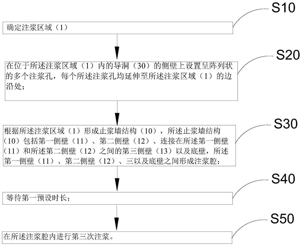
[0034] Such as Figure 1 to Figure 5 As shown, a plurality of pilot holes 30 are arranged below the existing building 20, and the lifting grouting method of the existing building of the present application includes:

[0035] Step S10: Determine the grouting area 1;

[0036] Step S20: setting a plurality of grouting holes in an array on the side wall of the guide hole 30 located in the grouting area 1, each grouting hole extending to the edge of the grouting area 1;

[0037] Step S30: Form a grout-stop wall structure 10 according to the grouting area 1. The grout-stop wall structure 10 includes a first side wall 11, a second side wall 12, and a first side wall connected between the first side ...


PUM


Abstract

The invention provides a lifting grouting method for an existing building. The lifting grouting method comprises the steps that step S10, a grouting area is determined; step S20, a plurality of grouting holes in an array shape are formed in the side wall of a pilot tunnel located in the grouting area, and each grouting hole extends to the edge of the grouting area; step S30, a grout stop wall structure is formed according to the grouting area, the grout stop wall structure comprises a first side wall, a second side wall, a third side wall connected between the first side wall and the second side wall, and a bottom wall, and a grouting cavity is formed among the first side wall, the second side wall, the third side wall and the bottom wall; step S40, a first preset duration is waited; and step S50, third-time grouting is conducted in the grouting cavity. According to the technical scheme, the problem that an existing building is prone to sedimentation in the prior art can be effectively solved.

Description

technical field [0001] The invention relates to the field of tunnel excavation, in particular to a lifting grouting method for an existing building. Background technique [0002] At present, in the process of tunnel excavation, the situation that the tunnel needs to pass through the existing buildings will be encountered, especially in the process of subway tunnel excavation, it is often encountered that it is necessary to dig a new tunnel under the already dug tunnel, so as to This forms the hub station of the transfer line. At this time, the tunnel that has been dug is the existing building, and the tunnel that needs to be newly excavated is called the lower increase of the existing building. During the construction of the lower storey, the settlement of the existing building needs to be strictly controlled. At present, advance grouting is generally carried out before the excavation of the pilot tunnel of the lower storey, and the initial support is carried out after the ...

Claims


Application Information

Patent Timeline
IPC IPC(8): E02D35/00E02D15/00
CPCE02D35/00E02D15/00
Inventor 雷升祥张志伟薛峰王华伟梁尔斌尤强郑凯靳德勇刘小勇孙孝锋
Owner CHINA RAILWAY SHISIJU GROUP CORP
Learn More