
Shaftless electric engine for aircraft, control method and aircraft

An electric engine and aircraft technology, which is used in aircraft parts, aircraft power transmission, aircraft power units, etc., can solve problems such as narrow use range, limit efficiency, sound pollution, etc., to avoid speed limit and power output limit, The effect of high energy use efficiency and avoidance of noise pollution

Active Publication Date: 2021-07-09
AERO ENGINE ACAD OF CHINA
View PDF9 Cites 4 Cited by
  • Summary
  • Abstract
  • Description
  • Claims
  • Application Information

AI Technical Summary

Problems solved by technology

[0002] Traditional aviation turboshaft engines or turboprop engines have complex structures, large volumes, extreme efficiency, high energy consumption, power output is limited by the shafting structure, the speed of fans and turbines is limited by the shafting structure, and the noise is loud when rotating. Pollution and other issues, not only the scope of use is narrow, but also unable to meet the high demand for environmental protection and high efficiency in the future

Method used


Image

  • Shaftless electric engine for aircraft, control method and aircraft
  • Shaftless electric engine for aircraft, control method and aircraft
  • Shaftless electric engine for aircraft, control method and aircraft

Examples


Embodiment 1

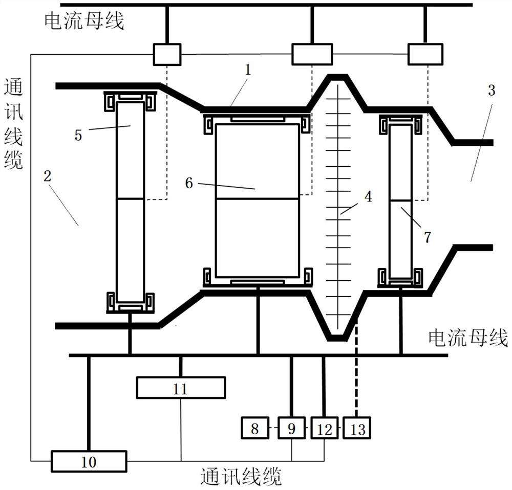
[0040] Such as Figures 1 to 10 As shown, the shaftless electric motor used for aircraft includes an engine casing 1, the front end of the engine casing 1 has an air inlet 2, and the rear end has a tail nozzle 3, and the distance between the air inlet 2 and the tail nozzle 3 is from front to back. The first group of magnetic levitation rotating mechanisms, the second group of magnetic levitation rotating mechanisms, and the third group of magnetic levitation rotating mechanisms are installed in sequence, and the combustion chamber 4 is between the second group of magnetic levitation rotating mechanisms and the third group of magnetic levitation rotating mechanisms;

[0041] The magnetic levitation rotating mechanism includes a casing 14, which is fixedly connected with the engine casing 1. There is an installation cavity in the casing 14 to provide an installation area for the stator. Stator, the stator is made of silicon steel material with good magnetic permeability, the sta...

Embodiment 2

[0057] Such as Figure 11 As shown, on the basis of Embodiment 1, each set of magnetic levitation rotating mechanism includes at least two stages of stators and blades 22 connected in series, that is, the fans of the magnetic levitation, the compressors of the magnetic levitation, and the turbogenerators of the magnetic levitation can be arranged as two or more stages in series. The structure of the stator and the blades 22, in this embodiment, is specifically set as a three-stage series structure to increase the output power.

[0058] An aircraft, the aircraft (not shown in the figure) is equipped with the shaftless electric motor described in Embodiment 1 or Embodiment 2.


PUM


Abstract

The invention relates to a shaftless electric engine for an aircraft, a control method and the aircraft. The front end of an engine shell is provided with an air inlet channel, the rear end of the engine shell is provided with an exhaust nozzle, three sets of magnetic suspension rotating mechanisms are sequentially installed between the air inlet channel and the exhaust nozzle, and a combustion chamber is formed between the second set and the third set; the magnetic suspension rotating mechanism comprises a shell, an annular stator iron core, an annular convex edge, a first coil, a second coil, a circular tube, blades, a cuboid permanent magnet and an annular permanent magnet. Through the three sets of magnetic suspension rotating mechanisms, the engine of the aircraft is motorized, low in noise and shaftless, the situation that a traditional shafting structure limits the rotating speed and power output of rotating parts is effectively avoided, and noise pollution is avoided.

Description

technical field [0001] The present disclosure relates to the field of piston technology, and more particularly to shaftless electric motors for aircraft. Background technique [0002] Traditional aviation turboshaft engines or turboprop engines have complex structures, large volumes, extreme efficiency, high energy consumption, power output is limited by the shafting structure, the speed of fans and turbines is limited by the shafting structure, and the noise is loud when rotating. Pollution and other issues not only narrow the scope of use, but also cannot meet the high demand for environmental protection and high efficiency in the future. [0003] Therefore, the present application proposes a shaftless electric motor for an aircraft. Contents of the invention [0004] In order to solve at least one of the above technical problems, the present disclosure provides a shaftless electric motor for an aircraft. [0005] The technical scheme that the present invention adopts ...

Claims


Application Information

Patent Timeline
IPC IPC(8): B64D33/00B64D35/00
CPCB64D33/00B64D35/00Y02T50/60
Inventor 姚轩宇蒋承志钱煜平王爱峰满运堃胡宣洋
Owner AERO ENGINE ACAD OF CHINA
Learn More