A pottery medium clay plate forming rolling mold assembly

A kind of medium mud plate and mold technology, applied in ceramic molding machines, mold auxiliary parts, molds, etc., can solve problems such as obvious marks, achieve the effect of simple operation, ensure surface flatness, and improve efficiency

Active Publication Date: 2022-03-11
NANJING XIAOZHUANG UNIV
View PDF5 Cites 0 Cited by
  • Summary
  • Abstract
  • Description
  • Claims
  • Application Information

AI Technical Summary

Problems solved by technology

[0005] The technical problem to be solved by the present invention is to provide a clay plate forming rolling method mold assembly in pottery art, which solves the problem that obvious traces will be formed at the position corresponding to the overlapping surface of the thickened block after the clay plate is pressed and formed, and the operation is simple , it has strong adaptability to the application scenarios of different numbers of thickened plates; it can also realize motorization, which can save manpower and ensure the uniformity of the rolling effect on the mud plate

Method used


Image

  • A pottery medium clay plate forming rolling mold assembly
  • A pottery medium clay plate forming rolling mold assembly
  • A pottery medium clay plate forming rolling mold assembly

Examples


Embodiment 1

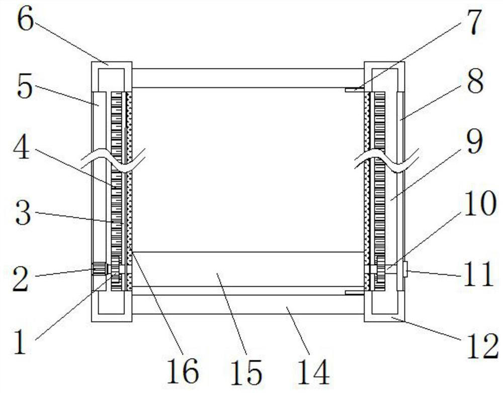
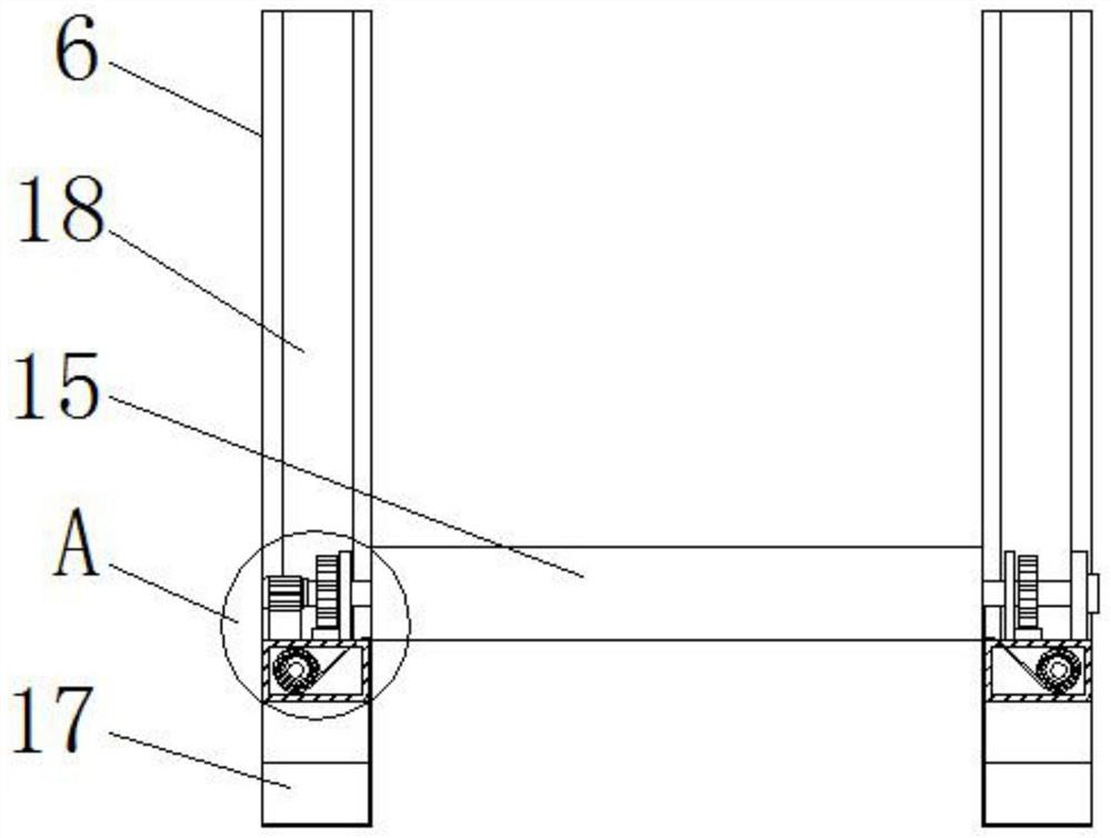
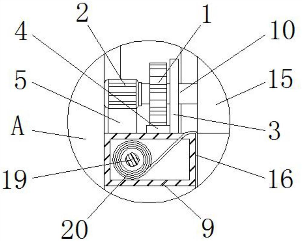
[0031] Such as figure 1 The shown mold assembly of clay plate forming rolling method in pottery art includes two sets of limit frames respectively located on both sides, and each set of limit frames includes a front stand 12 and a rear stand 6 oppositely arranged, and the front stand The end faces of the frame 12 and the rear stand 6 are all U-shaped, and a bottom plate 17 is fixedly connected between the front stand 12 and the corresponding rear stand 6; All are fixedly connected with fixed connecting plate 14 between back stand 6, as figure 1 , figure 2 and image 3 As shown, the top of each bottom plate 17 is overlapped with a top plate 9, and the top plate 9 is hollow inside and is provided with a central shaft 19 parallel to its length direction, as image 3 and Figure 4 As shown, the central rotating shaft 19 is wound with a covering cloth roll 20, and the beginning of the covering cloth roll 20 extends from the top surface of the top plate 9 to the outside and is ...

Embodiment 2

[0037] The difference between this embodiment and embodiment 1 is:

[0038] In this example, if Image 6 As shown, the upper and lower end surfaces of the thickened plate 21 are open, and the lower end surface of the thickened plate 21 is formed with a protruding edge 25 that is retracted and extends downward. The edge 25 is matched with the socket 26 , the upper end of the bottom plate 17 is provided with the socket 26 , and the lower end of the top plate 9 is formed with a protruding edge 25 . The bottom board 17, the thickened board 21, and the top board 9 are connected between every adjacent two boards through the plug-in fitting of the protruding edge 25 and the socket 26, which can prevent relative movement in the horizontal plane, thereby having It is beneficial to ensure the stability of the bar plate that is formed by the bottom plate 17, the thickened plate 21 and the top plate 9 to limit the mud plate, thereby ensuring the position-limiting effect on the mud plate....


PUM


Abstract

The invention discloses a mold assembly of clay plate forming and rolling method in pottery art, which belongs to the field of pottery moulds, and comprises a front stand, a back stand and a bottom plate fixedly connected between them; the top of each bottom plate is overlapped There is a top plate, the top plate is hollow inside and has a central rotating shaft parallel to its length direction, and a covering cloth roll is wound on the central rotating shaft, and the beginning of the covering cloth roll extends from the top surface of the top plate to the outside and is fixed. To the bottom surface of the bottom plate, a covering cloth layer is formed on the opposite sides of the two sets of top and bottom plates; both ends of the central shaft are fitted with ruler springs; between the top plate and the bottom plate, there are at least zero thickened plate. The invention solves the problem that obvious traces will be formed at the positions corresponding to the overlapping surfaces of the thickened blocks after the clay boards are pressed and formed, and the operation is simple, and the adaptability to the application scenarios of different numbers of thickened boards is strong; it can also realize electrification , which can save manpower and ensure the uniformity of the rolling effect on the mud plate.

Description

technical field [0001] The invention relates to the field of pottery moulds, in particular to a mold assembly of clay plate forming rolling method in pottery. Background technique [0002] Clay panel molding, as the name implies, is to roll mud blocks into clay panels manually or with a mud press, and then use these clay panels to shape. At first, you can start with a cylinder or a box shape, and then make some complicated works after you are proficient. When rolling the mud slab, put the mud on a piece of cloth and spread it from the center of the mud to the surroundings. Pay attention to the thickness of the mud to suit the needs of the work. Due to the large area of ​​the clay board, it is not easy to stand upright, so some auxiliary techniques can be used to shape it when making pottery. The works created by the clay tablet method are characterized by indirectness and clarity. Utilizing the softness of mud, it can be shaped like cloth, and using the hard characteristi...

Claims


Application Information

Patent Timeline
Patent Type & Authority Patents(China)
IPC IPC(8): B28B7/00B28B3/12
CPCB28B7/0097B28B7/0002B28B3/12
Inventor 张志雁
Owner NANJING XIAOZHUANG UNIV
Why Eureka
Try Eureka