


Quick Research
Generate reliable direction feasibility study reports for your R&D in just a few steps.

Technical Q&A
Discover and master advanced knowledge NOW. Basics, ideas, possibilities, all at once.

Find Solutions
As an expert in R&D theories, this can generate solutions to your technical problems instantly.

Evaluate Feasibility
Analyze your overall solution with one click, know your potential R&D risks in advance.

Monitor Landscape
Get weekly tech updates, stay abreast of the latest tech innovations and key insights.
A steel pipe inner wall derusting machine, derusting method, derusting mechanism and side plate
A technology for the inner wall of a steel pipe and a derusting machine, which is applied in the direction of abrasive jetting machine tools, metal processing equipment, used abrasive processing devices, etc., can solve problems such as low efficiency, multiple hoisting, and inability to move, and achieve the goal of improving efficiency Effect
- Summary
- Abstract
- Description
- Claims
- Application Information
AI Technical Summary
Problems solved by technology
Method used
Image

Examples
specific Embodiment approach 1
[0049] The following is a specific implementation of a steel pipe inner wall derusting machine.
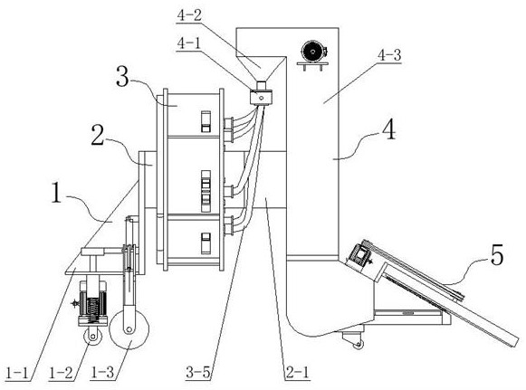
[0050] combine figure 1 As shown, a steel pipe inner wall derusting machine under this embodiment includes: a traveling mechanism 1, a frame body 2, a derusting mechanism 3, a lifting mechanism 4 and a separator 5, and the front end of the frame body 2 is provided with a traveling mechanism 1, the middle of the frame body 2 is provided with a derusting mechanism 3, the rear end of the frame body 2 is provided with a lifting mechanism 4, the lower end of the lifting mechanism 4 is connected with a separator 5, and the upper end of the lifting mechanism 4 is connected with the rust removing mechanism 3; A walking mechanism 1 is set on the derusting machine, so that the derusting machine is easy to move. When in use, the derusting is carried out by moving the derusting machine to the position of the steel pipe, which avoids the hoisting of the steel pipe. When the derusting machine i...
specific Embodiment approach 2
[0059] The following is a specific implementation of the derusting mechanism of a steel pipe inner wall derusting machine.
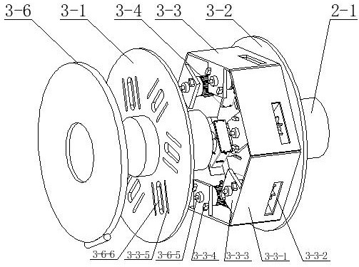
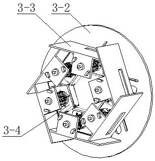
[0060] The derusting mechanism of a steel pipe inner wall derusting machine in this embodiment can be implemented alone or as a key technology in the first embodiment. combine figure 1 and figure 2 As shown, the derusting mechanism 3 includes: a front baffle 3-1, a rear baffle 3-2, a side plate 3-3, a blasting device 3-4 and a blasting device hose 3-5, the front The baffle plate 3-1 and the rear baffle plate 3-2 are circular plates coaxially arranged in parallel, and several side plates 3-3 are arranged between the front baffle plate 3-1 and the rear baffle plate 3-2, and several side plates 3-3 Plates 3-3 are respectively arranged along the sides of a regular polygon, and each side plate 3-3 is all slidably arranged on the front baffle plate 3-1 and the rear baffle plate 3-2, and the sliding direction of each side plate 3-3 All along the diagonal di...
specific Embodiment approach 3
[0062] The following is a specific implementation of a side plate of a steel pipe inner wall derusting machine.
[0063]The side plate of a steel pipe inner wall derusting machine in this embodiment can be implemented alone, or can be used as a key technology in the first embodiment, and the second embodiment can also be further limited.
[0064] combine figure 2 As shown, the side plate 3-3 includes: side plate body 3-3-1, shot blasting port 3-3-2, side connecting plate 3-3-3, connecting plate slider 3-3-4 and connecting plate The plate slider groove 3-3-5, the inner side of the side plate body 3-3-1 is fixedly connected with the blasting device 3-4, and the opening of the side plate body 3-3-1 and the blasting device 3-4 Correspondingly, a shot blasting port 3-3-2 is provided, and the side of the side plate body 3-3-1 close to the front baffle 3-1 is provided with a side connecting plate 3-3-3, on which the side connecting plate 3-3-3 The connecting plate slider 3-3-4 is ...
PUM
 Abstract
Description
Claims
Application Information
 - R&D Engineer
- R&D Manager
- IP Professional
- Industry Leading Data Capabilities
- Powerful AI technology
- Patent DNA Extraction
Browse by: Latest US Patents, China's latest patents, Technical Efficacy Thesaurus, Application Domain, Technology Topic, Popular Technical Reports.
© 2024 PatSnap. All rights reserved.Legal|Privacy policy|Modern Slavery Act Transparency Statement|Sitemap|About US| Contact US: help@patsnap.com