
Intensive care unit center oxygen supply breathing kit

An intensive care unit and oxygen supply technology, which is applied in nursing facilities, transportation and packaging, and vehicle ambulance, and can solve problems such as operational flexibility and unsatisfactory feedback efficiency

Inactive Publication Date: 2021-07-09
THE AFFILIATED HOSPITAL OF QINGDAO UNIV
View PDF1 Cites 0 Cited by
  • Summary
  • Abstract
  • Description
  • Claims
  • Application Information

AI Technical Summary

Problems solved by technology

[0003] The technical problem to be solved by the present invention is how to overcome the unsatisfactory operation flexibility and feedback efficiency of the existing central oxygen supply breathing equipment in the intensive care unit, and provide a central oxygen supply breathing set for the intensive care unit

Method used


Image

  • Intensive care unit center oxygen supply breathing kit
  • Intensive care unit center oxygen supply breathing kit
  • Intensive care unit center oxygen supply breathing kit

Examples


Embodiment approach 1

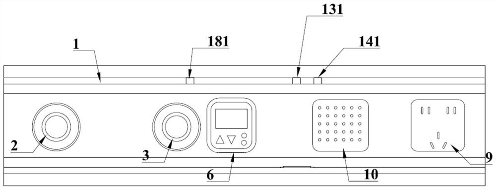
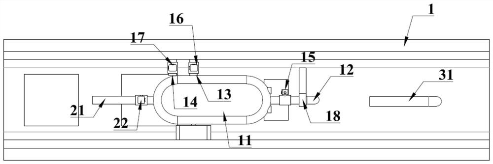
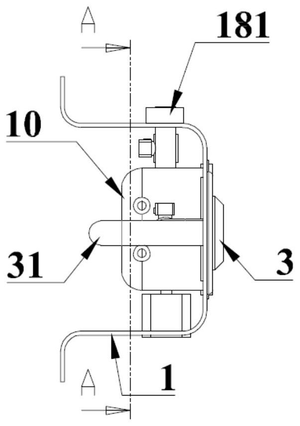
[0040] Implementation mode 1: if Figures 1 to 7 As shown, the central oxygen supply breathing set for the intensive care unit includes a housing 1 installed on the wall of the intensive care unit above the head of each bed in the intensive care unit, an oxygen interface 2 arranged on the housing, a negative pressure Interface 3, the inside of the housing 1 is provided with an oxygen inlet pipe 21 connected to the room inlet pipeline of the oxygen station, and a negative pressure inlet pipe 31 connected to the room inlet pipeline of the central negative pressure machine, wherein the housing 1 is provided with a gas mixing chamber 11 inside, one end of the gas mixing chamber 11 is connected with the oxygen inlet pipe 21, and the other end is connected with the oxygen interface 2 through the oxygen output pipe 12, and an increaser is provided above the gas mixing chamber 11. The thickening branch pipe 13 and the dilution branch pipe 14, the oxygen output pipe 12 is provided with...

Embodiment approach 2

[0047] Implementation mode 2: if Figure 8 As shown, the gas mixing chamber 11 is provided with a gas mixing pulsator 8, the bottom surface of the gas mixing chamber 11 is provided with a sealed bearing 19, and the gas mixing chamber 11 is provided with a gas mixing servo motor 81 below, and the gas mixing chamber 11 is provided with a gas mixing servo motor 81. The output shaft of the air servo motor 81 is connected with the air mixing pulsator 8 through a sealed bearing 19 . It is used to increase the mixing speed of the output gas after the enrichment or dilution gas is introduced, and to improve the accuracy of the sensor sensing signal. The gas mixing servo motor 81 is connected to the output end of the MCU processor 5 through a servo driver 82 , and the servo driver 82 takes power from the power converter 7 .

[0048] The central oxygen supply breathing set for the intensive care unit monitors the concentration and pressure of the output oxygen in real time in the gas m...


PUM


Abstract

The invention relates to an intensive care unit center oxygen supply breathing kit which comprises a shell, an oxygen connector and a negative pressure connector, an oxygen inlet pipe and a negative pressure inlet pipe are arranged in the shell, a gas mixing cavity is formed in the shell, a thickening branch pipe and a dilution branch pipe are arranged above the gas mixing cavity, and an output electromagnetic valve is arranged on an oxygen output pipe; a thickening electromagnetic valve and a diluting electromagnetic valve are respectively arranged on the thickening branch pipe and the diluting branch pipe; an electromagnetic valve driving module and an MCU processor are arranged on the inner side of the shell, a control panel is arranged on the outer side of the shell, and an oxygen concentration sensor and a pressure sensor are arranged in the gas mixing cavity. The intensive care unit central oxygen supply breathing kit is arranged in a gas mixing chamber to monitor the concentration and pressure of output oxygen in real time, and the oxygen output concentration is adjusted and set according to feedback signals; thus, a closed-loop feedback control loop is formed, and the oxygen concentration can be automatically controlled within a set threshold value, and a flow manual control function is realized; besides, additional functions such as a power socket and call talkback are provided.

Description

technical field [0001] The invention relates to the technical field of intensive care unit equipment, in particular to a central oxygen supply breathing suit for the intensive care unit. Background technique [0002] With the advancement of medical technology, the design and construction of intensive care units are equipped with oxygen supply and negative pressure supply pipelines to enter the room, while the indoor supporting facilities of intensive care units are mostly relatively simple in structure and installed on the wall. On the interface board directly connected to the above-mentioned inlet pipeline, the interface is usually blocked with a hole plug. Since the oxygen supply equipment and valve body are installed in the central oxygen station, when there is a need for oxygen inhalation, the oxygen concentration and flow must be controlled through the oxygen station. , the operating flexibility and feedback efficiency of output oxygen regulation are not ideal. Conten...

Claims


Application Information

Patent Timeline
IPC IPC(8): A61G12/00F17D1/04F17D3/01F17D5/00
CPCA61G12/005F17D1/04F17D3/01F17D5/005A61G2210/30A61G2203/34A61G2203/30
Inventor 孙强曲艳董海
Owner THE AFFILIATED HOSPITAL OF QINGDAO UNIV
Learn More