
Pumping system, pumping machine and cleaning method

A pumping system and pumping technology, applied in mechanical equipment, liquid displacement machinery, and parts of pumping devices for elastic fluids, etc., can solve the damage of pumping equipment parts, wear of delivery cylinders, and failure to replace them in time cleaning water etc.

Pending Publication Date: 2022-07-01
SANY AUTOMOBILE MFG CO LTD
View PDF8 Cites 0 Cited by
  • Summary
  • Abstract
  • Description
  • Claims
  • Application Information

AI Technical Summary

Problems solved by technology

[0002] At present, after the washing room of the pumping machinery on the market has been used for a long time, the cleaning water in the washing room will contain a lot of impurities, and if it is not cleaned in time, it will accelerate the damage of the pumping equipment components, such as the wear of the concrete seal or the wear of the delivery cylinder, thus Affect the normal operation of pumping equipment
In the related technology, the on-site staff need to judge whether the cleaning water in the washing room needs to be replaced according to the actual situation. However, due to the heavy on-site work tasks, the on-site staff tend to forget this work and fail to replace the cleaning water in time, resulting in pumping equipment components. damage

Method used


Image

  • Pumping system, pumping machine and cleaning method
  • Pumping system, pumping machine and cleaning method
  • Pumping system, pumping machine and cleaning method

Examples


Embodiment 1

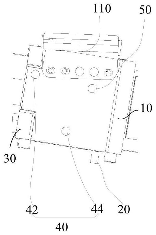
[0048] Specifically, as figure 1 As shown, in the first embodiment of the present invention, the drain valve 20 and the water injection valve 30 are electric valves. superior.

[0049] In the above setting, the drain valve 20 is located at the bottom of the washing chamber 10, which is convenient for the drain valve 20 to drain the washing water in the washing chamber 10, and the water injection valve 30 is located at the bottom of the washing chamber 10, which is convenient for the water injection valve 30 to fill the washing chamber 10. Therefore, it is ensured that the pumping system 110 can completely discharge the unsatisfactory washing water from the washing chamber 10 and refill the washing chamber 10 with clean washing water. This ensures that the on-site pumping equipment can work normally and the on-site pumping operation can be carried out smoothly.

[0050] Specifically, as figure 1 As shown, in the first embodiment of the present invention, the pumping system 1...

Embodiment 2

[0083] The second embodiment and the embodiment have the following differences:

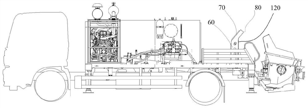
[0084] Specifically, as Figure 5 to Figure 8 As shown, in the second embodiment of the present invention, no water quality monitoring device 50 or particulate matter monitoring device is required, and the control component 60 does not have the function of judging whether the particle content of the washing water in the washing chamber 10 exceeds the standard.

[0085] Specifically, as Figure 8 As shown, in the second embodiment of the present invention, the control component 60 has a timing function. When the washing water in the washing room 10 is placed for a preset time, the control component 60 sends an alarm message to the display 80 .

[0086] Specifically, as Figure 8 As shown, in the second embodiment of the present invention, before step S70, the cleaning method further includes:

[0087] Step S11: The control component judges whether the washing water in the washing room exceeds t...


PUM


Abstract

The invention provides a pumping system, a pumping machine and a cleaning method. A conveying cylinder; the washing chamber is arranged between the main oil cylinder and the conveying cylinder; the drain valve is connected with the washing chamber; the water injection valve is connected with the washing chamber; the control assembly is connected with the drainage valve and the water injection valve so as to control opening and closing of the water injection valve and the drainage valve. According to the technical scheme, the control assembly can achieve replacement of the cleaning water in the washing chamber, so that the pumping system has the function of automatically replacing the cleaning water, manual replacement of the cleaning water in the washing chamber in the prior art is not needed, and the cleaning efficiency is improved. The problem that parts of the pumping equipment are damaged due to the fact that on-site workers forget to replace the cleaning water is solved, and therefore it is guaranteed that the on-site pumping equipment can work normally, and on-site pumping operation can be carried out smoothly.

Description

technical field [0001] The present invention relates to the technical field of pumping machinery cleaning, and in particular, to a pumping system, a pumping machinery and a cleaning method. Background technique [0002] At present, after the washing chamber of the pumping machinery on the market is used for a long time, the washing water in the washing chamber will contain a large amount of impurities. If it is not cleaned in time, the damage to the parts of the pumping equipment will be accelerated, such as the wear of the concrete seal or the wear of the conveying cylinder, thereby Affect the normal operation of pumping equipment. In the related art, the on-site staff needs to judge by themselves whether the cleaning water in the washing room needs to be replaced according to the actual situation. However, due to the heavy on-site work tasks, the on-site staff easily forgets this work and does not replace the cleaning water in time, thus causing pumping equipment component...

Claims


Application Information

Patent Timeline
IPC IPC(8): F04B53/00F04B49/22F04B49/06F04B49/10
CPCF04B53/00F04B49/22F04B49/06F04B49/10
Inventor 徐兆杨赵志强张启军
Owner SANY AUTOMOBILE MFG CO LTD
Learn More