
Oral cavity examination device for stomatology department

An inspection device and stomatology technology, applied in the field of oral inspection devices used in stomatology, can solve the problems of accidental injury in the inspection of the oral cavity, low inspection efficiency, manual lighting, etc.

Pending Publication Date: 2021-07-09
尹广建
View PDF0 Cites 0 Cited by
  • Summary
  • Abstract
  • Description
  • Claims
  • Application Information

AI Technical Summary

Problems solved by technology

[0003] However, when the existing technology checks the mouth, because the length of the oral equipment cannot be flexibly adjusted for inspection, it will cause accidental injury in the process of checking the mouth, resulting in a relatively low inspection efficiency to a certain extent, and people are in the process of observing the mouth. In the middle, the manual lighting makes people have a certain deviation in vision, which leads to certain fluctuations in the quality of observation and inspection.

Method used


Image

  • Oral cavity examination device for stomatology department
  • Oral cavity examination device for stomatology department
  • Oral cavity examination device for stomatology department

Examples


Embodiment 1

[0031] A kind of oral examination device for stomatology, such as figure 1 , figure 2 , image 3 and Figure 4 As shown, it includes a support frame 1, a handle 2, a support mechanism 3 and a lifting mechanism 4, the support frame 1 rear lower side is provided with a support mechanism 3, the support mechanism 3 front side is provided with a handle 2, and the support frame 1 rear upper side is provided with a There is a lifting mechanism 4.

[0032] When people need to check the oral cavity, they can use this device. First, place the device in the oral cavity, and manually rotate the supporting mechanism 3 clockwise to a certain degree. Then the supporting mechanism 3 will be moved up to a certain height, which is convenient for people to check the oral cavity.

[0033] The support mechanism 3 includes a first support block 30, a first torsion spring 31, a rotating rod 32 and a brace 33. The rear side of the support frame 1 and the lifting mechanism 4 are provided with a b...

Embodiment 2

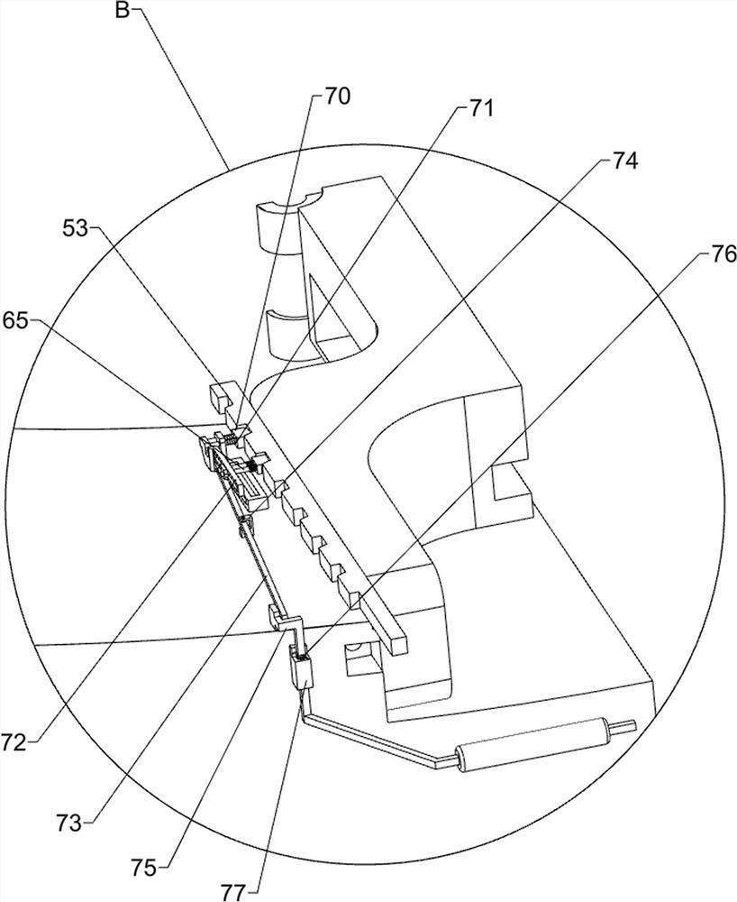
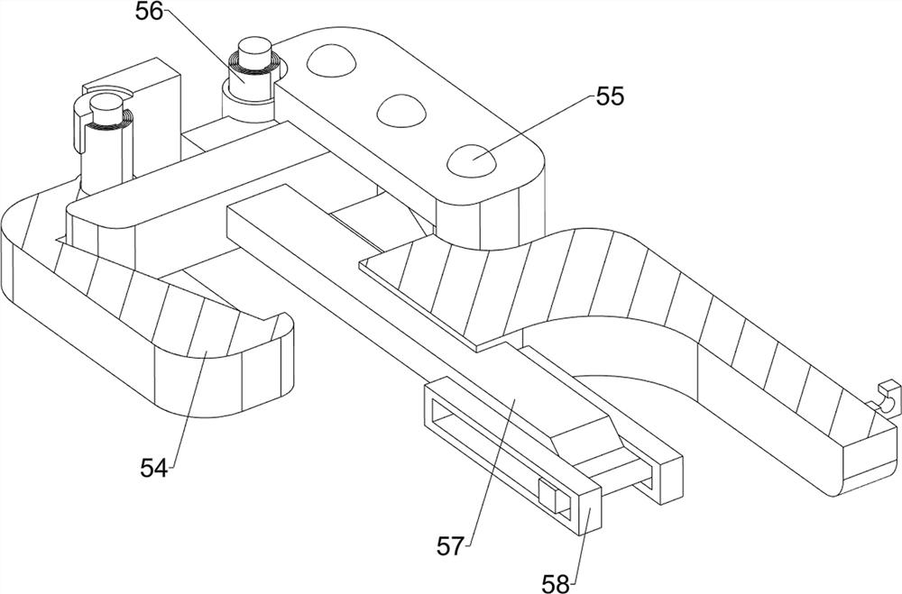
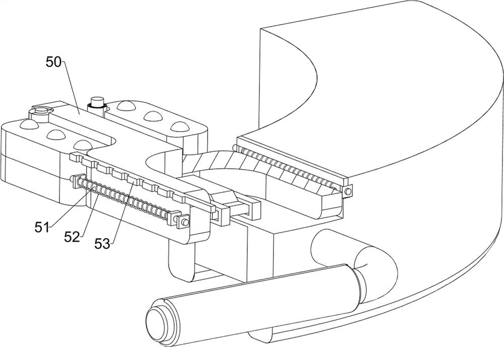
[0038] On the basis of Example 1, such as Figure 5 , Figure 6 , Figure 7 , Figure 8 , Figure 9 , Figure 10 and Figure 11 As shown, a tongue depressor assembly 5 is also included, and the tongue depressor assembly 5 includes a telescopic plate 50, a first guide rod 51, a first elastic spring 52, a rack 53, a spatula 54, a ball 55, a scroll spring 56, Sliding bar 57 and fixed slideway 58, the center of the lower side of the dental cover 33 lower side is symmetrically provided with fixed slideway 58, sliding type is provided with sliding bar 57 between the fixed slideway 58, and the left and right sides in the middle part of dental cover 33 are all provided with first The guide rod 51, the first guide rod 51 is equipped with a telescopic plate 50 slidingly, and the first elastic spring 52 is connected between the telescopic plate 50 and the lower brace 33, and the first elastic spring 52 is set on the first guide rod. 51, the outside of the telescopic plate 50 is pro...


PUM


Abstract

The invention relates to an oral cavity examination device, in particular to an oral cavity examination device for stomatology department. The technical problem to be solved is to provide the oral examination device for the stomatology department, the length of which can be flexibly adjusted and a fixed illuminating lamp. According to the technical scheme, the oral cavity examination device comprises a supporting frame, a handle, a supporting mechanism and a lifting mechanism; a supporting mechanism is arranged at the lower side of the supporting frame, a handle is arranged on the front side of the supporting mechanism, and a lifting mechanism is arranged on the upper side of the rear portion of the supporting frame. The length of the device can be flexibly adjusted, and a lighting lamp can be fixed; a transmission assembly drives the clamping assembly to move backwards, a clamping assembly drives the tongue pressing assembly to move into the oral cavity, if the tongue cannot be blocked through first-time movement, a tongue pressing assembly can be moved again according to the situation, and the effect that the length of the tongue pressing assembly can be flexibly adjusted is achieved.

Description

technical field [0001] The invention relates to an oral cavity inspection device, in particular to an oral cavity inspection device for the department of stomatology. Background technique [0002] Teeth are a part of the oral cavity. With the continuous innovation of medical equipment, people nowadays pay as much attention to the oral cavity as to their physical health. The oral cavity is the beginning part of the digestive tract. . [0003] However, when the existing technology checks the mouth, because the length of the oral equipment cannot be flexibly adjusted for inspection, it will cause accidental injury in the process of checking the mouth, resulting in a relatively low inspection efficiency to a certain extent, and people are in the process of observing the mouth. Among them, manual lighting causes people to have a certain deviation in vision, resulting in certain fluctuations in the quality of observation and inspection. [0004] In view of the problems existing ...

Claims


Application Information

Patent Timeline
Patent Type & Authority Applications(China)
IPC IPC(8): A61B1/24A61B1/06A61B90/16
CPCA61B1/24A61B1/0684A61B90/16
Inventor 尹广建
Owner 尹广建
Learn More