


Quick Research
Generate reliable direction feasibility study reports for your R&D in just a few steps.

Technical Q&A
Discover and master advanced knowledge NOW. Basics, ideas, possibilities, all at once.

Find Solutions
As an expert in R&D theories, this can generate solutions to your technical problems instantly.

Evaluate Feasibility
Analyze your overall solution with one click, know your potential R&D risks in advance.

Monitor Landscape
Get weekly tech updates, stay abreast of the latest tech innovations and key insights.
A Pumping Unit Motor Regulator Convenient for Maintenance of Pumping Units
A technology for motors and regulators, which is applied in the field of pumping unit motor regulators, can solve problems such as time-consuming and laborious, belt wear, and failure to ensure the correct position of the motor, and achieve the effects of ensuring stability, ingenious structure, and meeting belt maintenance requirements
- Summary
- Abstract
- Description
- Claims
- Application Information
AI Technical Summary
Problems solved by technology
Method used
Image

Examples
Embodiment 1
[0030] Embodiments of the present invention will be specifically described below in conjunction with the accompanying drawings.
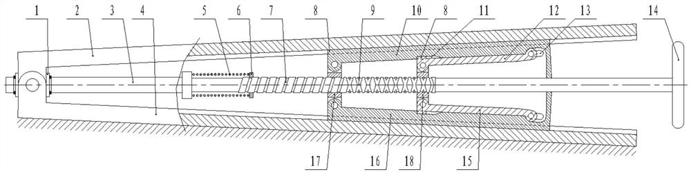
[0031] like figure 1 As shown, this embodiment includes an upper plate 2, a lower plate 4, a lead screw 3 and a wedge assembly; one end of the lead screw 3 is provided with a rotating sleeve 1 through a circlip, and the other end of the lead screw 3 is fixedly equipped with a handwheel 14; One end of the upper plate 2 and the lower plate 4 is respectively hinged on the upper and lower sides of the rotating sleeve 1; The bottom moves between the upper plate 2 and the lower plate 4. During installation, the lower plate 4 is fixedly installed on the base of the pumping unit, and the motor is fixedly installed on the upper plate 2 . When in use, the screw 3 is rotated by rotating the hand wheel 14, and then drives the wedge-shaped assembly to move, thereby adjusting the included angle between the upper plate 2 and the lower plate 4 .
[0032] like f...
Embodiment 2
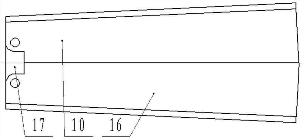
[0043] like Figure 4 and Figure 5 As shown, the difference between this embodiment and the first embodiment is that a bar-shaped hole 13 is added to the nut B18, and a ratchet 19 is added at the junction of the upper shell 10 and the lower shell 16.
[0044] Before the upper and lower support arms are set up, the above changes make the upper case 10 hooked on the lower case 16 through the ratchet 19, which is beneficial to ensure the positional stability between the upper plate 2 and the lower plate 4, and the upper and lower support arms In the initial stage of arm support, the upper shell 10 and the lower shell 16 are dislocated, so that the two can be separated, so that the upper and lower arms are set up. It should be noted that, in order to displace the upper casing 10 and the lower casing 16, the length of the strip-shaped hole 13 on the lower casing 16 must be greater than the length of the strip-shaped hole 13 on the upper casing 10.
[0045] After the improvement,...
PUM
 Abstract
Description
Claims
Application Information
 - R&D Engineer
- R&D Manager
- IP Professional
- Industry Leading Data Capabilities
- Powerful AI technology
- Patent DNA Extraction
Browse by: Latest US Patents, China's latest patents, Technical Efficacy Thesaurus, Application Domain, Technology Topic, Popular Technical Reports.
© 2024 PatSnap. All rights reserved.Legal|Privacy policy|Modern Slavery Act Transparency Statement|Sitemap|About US| Contact US: help@patsnap.com