Engine control system of tilt-rotor unmanned aerial vehicle

A technology of tilting rotor and control system, applied in the direction of engine control, machine/engine, electric controller, etc., can solve the problems of unmanned aerial vehicle, oil-powered system limitation, etc.

Active Publication Date: 2021-07-06
SHENYANG INST OF AUTOMATION - CHINESE ACAD OF SCI
View PDF23 Cites 0 Cited by
  • Summary
  • Abstract
  • Description
  • Claims
  • Application Information

AI Technical Summary

Problems solved by technology

But these studies were all built on small electric UAV models and cannot be used for gas-powered UAVs
The hydraulic system is very different from the electric motor in terms of response and matching. In the transition state of tilting, the hydraulic system is restricted a lot; in addition, there is a contradiction between the overshoot and steady-state performance of the traditional PID system, so it needs to be improved. systematic research

Method used


Image

  • Engine control system of tilt-rotor unmanned aerial vehicle
  • Engine control system of tilt-rotor unmanned aerial vehicle
  • Engine control system of tilt-rotor unmanned aerial vehicle

Examples


Embodiment Construction

[0033] The present invention will be further described in detail below in conjunction with the accompanying drawings and embodiments.

[0034] In order to make the above objects, features and advantages of the present invention more comprehensible, specific implementations of the present invention will be described in detail below in conjunction with the accompanying drawings. In the following description, numerous specific details are set forth in order to provide a thorough understanding of the present invention. However, the present invention can be implemented in many other ways different from those described here, and those skilled in the art can make similar improvements without violating the connotation of the invention, so the present invention is not limited by the specific implementation disclosed below.

[0035] The system control composition of the present invention is:

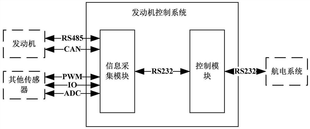
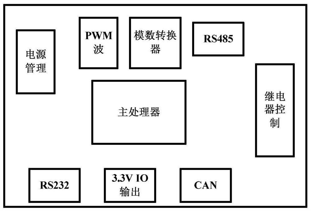
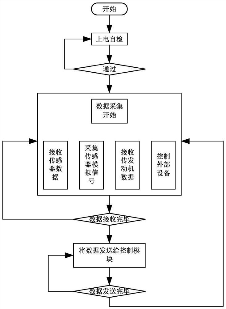
[0036] An engine control system for a tilt-rotor UAV, including two parts: an information acq...


PUM


Abstract

The invention relates to an engine control system of a tilt-rotor unmanned aerial vehicle, which is suitable for a medium-sized oil-driven tilt-rotor unmanned aerial vehicle. The system comprises an information acquisition module and a control module. The information acquisition module is mainly used for acquiring various parameters of an engine and interacting information with the engine ECU system and the control module; and the control module adopts a control strategy combining sliding mode control and PID control according to various parameters of the engine obtained by the information acquisition module so as to adapt to a helicopter mode, a fixed wing mode and a transition mode between a helicopter and a fixed wing of the unmanned aerial vehicle.

Description

technical field [0001] The invention relates to the field of unmanned aerial vehicle flight control, in particular to a tilt rotor unmanned aerial vehicle engine control system. Background technique [0002] On the premise of ensuring the high-speed cruise of fixed wings, the tilt-rotor aircraft has the vertical take-off and landing capability of the rotor aircraft. The take-off and landing are less restricted by the site, have high flexibility, and have broad application fields in the military. The United States has continued to develop XV-15, V-22 and other series of tilting rotor aircraft. Among them, V22 has a tilting mechanism at both ends of the wing to push the rotor upward or forward, which are used for vertical take-off and landing of helicopters or hovering and Fixed-wing flight phase. The development of tilt-rotor drones is relatively late. Based on the V22 "Osprey" manned tilt-rotor aircraft, the V247 drone developed by Bell Labs in the United States has recentl...

Claims


Application Information

Patent Timeline
IPC IPC(8): G05B11/42B64D31/00F02D29/02
CPCG05B11/42B64D31/00F02D29/02
Inventor 何玉庆周浩谷丰李鹏孙晓舒杨丽英
Owner SHENYANG INST OF AUTOMATION - CHINESE ACAD OF SCI
Why Eureka
Try Eureka