Double-angle self-switching multifunctional handle for doors and windows
A dual-angle, multi-functional technology, applied in the field of door and window handles, can solve the problems of single handle function, inability to switch, and limited application range of handles, etc.
- Summary
- Abstract
- Description
- Claims
- Application Information
AI Technical Summary
Problems solved by technology
Method used
Image
Examples
Embodiment 1
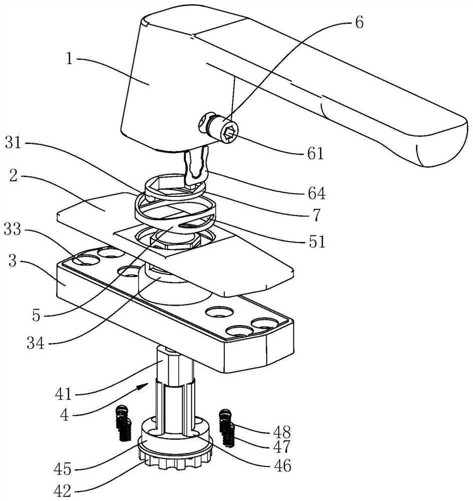
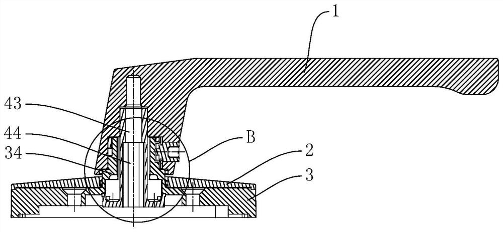
[0026] The doors and windows of Example 1 were handled by a double angle self-switting, such as Figure 1 - Figure 9 Distance figure 1 The direction in the middle facing is before, the direction of the downward is figure 2 In the direction of the left direction, the direction of the right direction is, and the front and rear left and right directions of each part are referred to. The multi-function hand includes the handle 1, the cover 2, and the base 3, and the cover plate 2 is disposed on the front side of the base 3, and several mounting holes 33 are opened on the base 3, and several mounting holes 33 are used to mount several screws (not in the figure. Demarative), the base 3 is fixed to the door window fan on the door window fan (not shown) by a plurality of screws, and the handle 1 is fixed to a gear turntable 4 including the connecting shaft 41 of the front and rear integral coaxial settings. 41 The gear 42, the gear 42 is disposed in the inner side of the base 3, and the ge...
Embodiment 2
[0030] The multi-function handle of the door and window of Example 2 is switched with a double angle, and the difference from the first embodiment is that in Example 2, the second curved limit boss 32 is integrated into the outer wall of the limit shaft 34, the first The curved limit boss 31 is integrated to the upper half of a certain position of the circular ring 7, and the inner bore of the positioning of the circular ring 7 is a hexagon hole, and the front end of the limit shaft 34 is a hexagon adapted to the hexagonal hole. The positioning ring 7 is set and the handle 1 is pressed to fix the front end of the limit shaft 34, and the rear end of the limit shaft 34 is provided with an arc-shaped positioning boss 36 with the lower half of the positioning circle 7. The lower half of the positioning of the circular ring 7, the arc-shaped positioning boss 36 and the outer circle of the limit shaft 34 are around the second arc groove 37, and the second arc groove 37 is axially along ...
PUM
 Abstract
Description
Claims
Application Information
 - R&D Engineer
- R&D Manager
- IP Professional
- Industry Leading Data Capabilities
- Powerful AI technology
- Patent DNA Extraction
Browse by: Latest US Patents, China's latest patents, Technical Efficacy Thesaurus, Application Domain, Technology Topic, Popular Technical Reports.
© 2024 PatSnap. All rights reserved.Legal|Privacy policy|Modern Slavery Act Transparency Statement|Sitemap|About US| Contact US: help@patsnap.com


