A back iron slotted disk permanent magnet transmission device
A permanent magnet transmission device and disk-type technology, which is applied in the transmission field, can solve the problems of obvious magnetic leakage and low utilization rate of magnetic energy, and achieve the effects of easy installation and operation, saving production costs, and facilitating large-scale production and manufacturing
- Summary
- Abstract
- Description
- Claims
- Application Information
AI Technical Summary
Problems solved by technology
Method used
Image

Examples
Embodiment 1
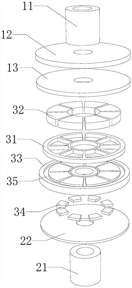
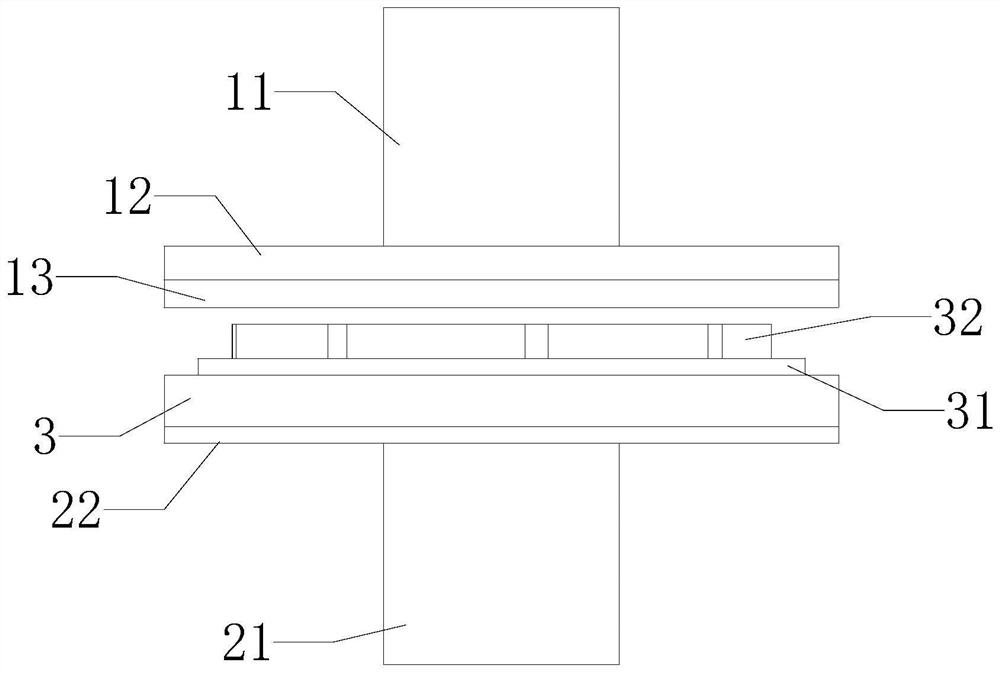
[0034] like figure 1 , figure 2 As shown, this embodiment provides a disk-type permanent magnet transmission device with a slotted back iron, which is used to transmit power between two shaft bodies. The two shaft bodies include the first shaft body 11 and the second shaft body 21 . The first shaft body 11 and the second shaft body 21 are coaxially arranged. The transmission device includes: a top plate 12 , a vortex plate 13 , a bottom plate 22 , and a fixing mechanism 3 .
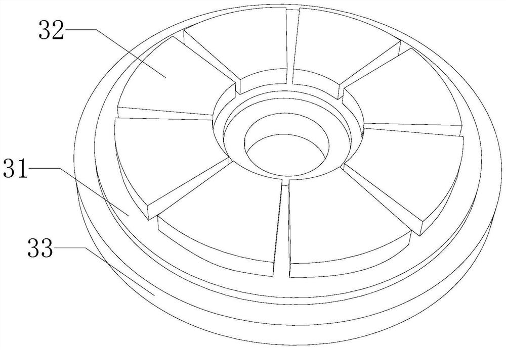
[0035] please combine image 3 , in this embodiment, in order to facilitate installation, the shaft body 11, the top plate 12, the eddy current plate 13, the mounting plate 33, the bottom plate 22 and the middle part of the shaft body 2 21 are all provided with through holes, and a plurality of said The inner diameters of the through holes are all equal. The outer diameters of the top plate 12 , the vortex plate 13 , the mounting plate 33 and the bottom plate 22 are all equal. The top plate 12 is c...
Embodiment 2
[0046] see Figure 9 , This embodiment provides an installation method, and the installation method can be applied to the disk-type permanent magnet transmission device with the back iron slotted in the embodiment 1. The installation method includes:
[0047] Step S1 : first coaxially dispose the first shaft body and the top plate 12 , and then fix the first shaft body 11 and the top plate 12 by welding or other means.
[0048] Step S2: First, coaxially dispose the top plate 12 and the eddy current plate 13, and then fixedly connect the eddy current plate 13 and the top plate 12 by means of gluing or the like.
[0049] Step S3: firstly coaxially dispose the chassis 22 and the second axle body 21, and then fix the chassis 22 and the second axle body 21 by welding or other means.
[0050] Step S4: firstly, the plurality of auxiliary magnetic poles 34 are classified and embedded in the plurality of installation grooves 36 on the installation plate 33 at intervals, then the inst...
Embodiment 3
[0054] The difference between this embodiment and Embodiment 1 lies in that, on the basis of the existing structure of Embodiment 1, this embodiment is additionally provided with a casing. The shell includes: a first shell and a second shell.
[0055] The first shell and the second shell are arranged separately. Among them, the shaft body 11, the top plate 12 and the eddy current plate 13 can all be installed inside the casing one. The second shaft body 21 , the chassis 22 and the fixing mechanism 3 can all be installed inside the second casing. Shell 1 and shell 2 can also be made of light material with paramagnetic properties, which can protect the entire transmission device and the two shafts, which can prevent dust from entering the internal structure of the transmission device and prevent external objects from colliding with the internal structure. It can also reduce the degree of oxidation and aging of the internal structure of the transmission device, thereby prolongi...
PUM
 Abstract
Description
Claims
Application Information
 - R&D
- Intellectual Property
- Life Sciences
- Materials
- Tech Scout
- Unparalleled Data Quality
- Higher Quality Content
- 60% Fewer Hallucinations
Browse by: Latest US Patents, China's latest patents, Technical Efficacy Thesaurus, Application Domain, Technology Topic, Popular Technical Reports.
© 2025 PatSnap. All rights reserved.Legal|Privacy policy|Modern Slavery Act Transparency Statement|Sitemap|About US| Contact US: help@patsnap.com