An energy-saving and environment-friendly building roof structure and its use method

A roof structure, energy saving and environmental protection technology, which is applied to building components, building structures, roofs, etc., can solve the problems of excessive dust, poor dust effect, and poor production environment in workshops, achieving low cost, maintaining air permeability, and simple structure. Effect

Active Publication Date: 2022-07-01
广东中颢工程设计有限公司
View PDF5 Cites 0 Cited by
  • Summary
  • Abstract
  • Description
  • Claims
  • Application Information

AI Technical Summary

Problems solved by technology

[0002] The factory area is relatively large, and the top is usually covered with color steel plates. During production operations, especially in the stone and wood processing industries, a huge amount of dust will be generated. These dusts permeate the interior of the factory building and float on the top. After the production is over and there is no wind, the dust begins to sink to the ground, resulting in a poor production environment in the factory
After we investigated the stone processing units, we found that most of the staff have obvious respiratory diseases, and some staff also have eye diseases. The reason is that there is a lot of dust in the working environment; while the traditional installation in The exhaust equipment on the wall can only exhaust the indoor air to the outside, but the effect on the dust suspended in the upper part of the factory building is very poor

Method used


Image

  • An energy-saving and environment-friendly building roof structure and its use method
  • An energy-saving and environment-friendly building roof structure and its use method
  • An energy-saving and environment-friendly building roof structure and its use method

Examples


Embodiment 1

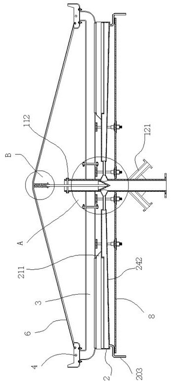
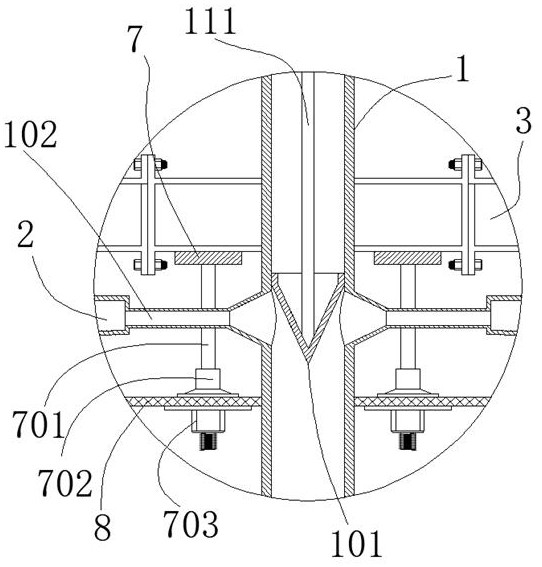
[0040] An energy-saving and environmentally friendly building roof structure, comprising a plurality of vertical columns 1 arranged at equal distances in the longitudinal direction, and a connecting rod assembled between two longitudinally adjacent vertical columns 1; There is a baffle plate 101 , and two left and right air outlet pipes 102 are arranged below the baffle plate 101 at the outer wall of the upright column 1 ; Air box 2, the air outlet duct 102 is connected to the air outlet box 2, and the air mixed with particulate matter entering upward from the column 1 enters the air outlet box 2 through the air outlet duct 102; The top of the air outlet box 2 is provided with a through slot 201, and the interior of the through slot 201 is provided with a screen 202 for screening particulate matter; The screen 202 intercepts and captures; the bottom of the air outlet box 2 is provided with a water outlet pipe 203 at the end away from the air outlet pipe 102; the outer wall of ...

Embodiment 2

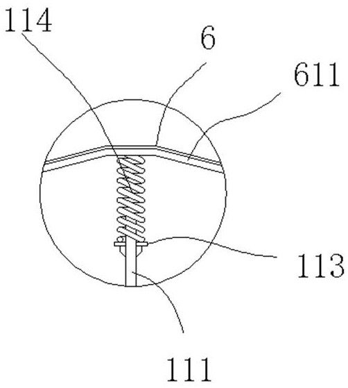
[0042] The height of the end of the water tank 4 away from the cover plate 6 is higher than the height of the other three sides of the water tank 4. When the rain is heavy, the rainwater sliding down the cover plate 6 passes through the side wall of the water tank 4. After blocking, it falls into the water tank 4; when the amount of rainwater is large, the water flow sliding down the cover plate 6 has a certain flow rate, so the height of the side of the water tank 4 corresponding to the cover plate 6 is relatively high, which can block the water flow .

Embodiment 3

[0044] A cover 211 is provided above the air outlet box 2 , an opening 232 is formed at the end of the cover 211 away from the upright column 1 , and an assembly groove for assembling the water distribution plate 5 is provided on the upper end of the cover 211 212; The above structure is mainly to guide the discharged air. After the above structure is adopted, the air that is pumped to the outside can only be discharged from the opening 232. When the water is kept dripping from the water distribution plate 5, the water and the The contact efficiency of the air can achieve the purpose of further dust reduction, and at the same time, the above structure can also prevent the discharged particulate matter from accumulating under the cover plate 6 .


PUM


Abstract

The invention discloses an energy-saving and environment-friendly building roof structure and a method for using the same, comprising a plurality of vertical columns arranged at equal distances in the longitudinal direction, and a connecting rod assembled between two longitudinally adjacent vertical columns; the vertical columns are hollow The pipe fitting is provided with a baffle plate inside, and two left and right air outlet pipes are arranged below the baffle plate at the outer wall of the column; an air box, the air outlet pipe is connected to the air outlet box, and the air mixed with particulate matter entering upward from the vertical column enters the air outlet box through the air outlet pipe; The top is provided with a through groove, and the interior of the through groove is set with a screen for screening particulate matter; the device can cooperate with the exhaust equipment to uniformly discharge the dust that pervades the height of the workshop, and can also discharge the discharged dust. Particulate matter is disposed of in an environmentally friendly manner.

Description

technical field [0001] The invention relates to an energy-saving and environment-friendly building roof structure and a use method thereof. Background technique [0002] The factory area of ​​the factory building is large, and its top is usually covered with color steel plates. During the production operation, especially in the stone and wood processing industries, a huge amount of dust will be generated. These dusts diffuse inside the factory building and float above. After the production is over and there is no wind, the dust begins to sink to the ground, resulting in a poor production environment in the workshop. After investigating the stone processing units, we found that most of the staff have obvious respiratory diseases, and some staff also have eye diseases. The reason is that there is a lot of dust in the working environment; while the traditional installation in The exhaust equipment on the wall can only extract the indoor air to the outside, and the effect on th...

Claims


Application Information

Patent Timeline
Patent Type & Authority Patents(China)
IPC IPC(8): E04B7/00E04D13/00E04D13/04E04D13/158B01D46/00B01D46/10B01D46/66
CPCE04B7/00E04D13/00E04D13/04E04D13/1585B01D46/0035B01D46/10B01D46/66B01D46/681
Inventor 周建旺卜勇沈哲艺陈杨
Owner 广东中颢工程设计有限公司
Why Eureka
Try Eureka