Efficient drilling equipment for brush plate machining

A kind of drilling equipment and high-efficiency technology, which is applied in the field of high-efficiency drilling equipment for brush plate processing, can solve the problems of low efficiency and manpower consumption, and achieve the effects of improving work efficiency, stable operation, and convenient adjustment

Active Publication Date: 2021-07-02
安徽三和刷业股份有限公司
View PDF32 Cites 0 Cited by
  • Summary
  • Abstract
  • Description
  • Claims
  • Application Information

AI Technical Summary

Problems solved by technology

[0005] The purpose of the present invention is to solve the problem of labor-intensive and low efficiency in the prior art, and propose a high-efficiency drilling equipment for brush plate processing

Method used


Image

  • Efficient drilling equipment for brush plate machining
  • Efficient drilling equipment for brush plate machining
  • Efficient drilling equipment for brush plate machining

Examples


Embodiment 1

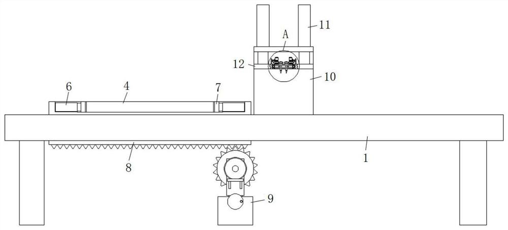
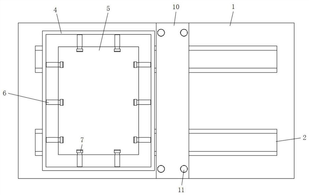
[0033] refer to Figure 1-6, a high-efficiency drilling equipment for brush plate processing, including a workbench 1, the top of the workbench 1 is provided with a mounting groove-2 running through the front and rear sides, the inner wall of the mounting groove-2 is slidably connected with a mounting block-3, and four mounting blocks-1 3. The top surface of the working disk 4 is fixedly connected with the working disk 4, and the top surface of the working disk 4 is provided with a fixing groove 5, and the side wall of the fixing groove 5 is fixed with the electric telescopic rod-6 through screws, and the output ends of the electric telescopic rod-6 are connected by screws An extruding block 7 is fixedly connected, a rack 8 is fixedly connected between the bottom surfaces of the two mounting blocks 1-3 at the front and rear ends, a drive mechanism 9 is arranged on the lower side of the middle part of the workbench 1, and a mounting mechanism 9 is fixed on the middle part of the...

Embodiment 2

[0036] Such as figure 1 with 6 As shown, this embodiment is basically the same as Embodiment 1. Preferably, the driving mechanism 9 includes a fixed seat 91, and the top surface of the fixed seat 91 is provided with a bar-shaped groove, and the inner wall of the front and rear sides of the bar-shaped groove is rotatably connected with a threaded rod 92. The threaded rod 92 front and rear side outer walls are all fixedly connected with a bar block 93 by threads, and the top surface of the bar block 93 is fixedly connected with a mounting seat 94 by screws, and a driving rod 95 is rotationally connected between the two mounting seats 94, and the outer wall of the driving rod 95 passes through Drive gear 96 is fixedly connected with screw, and the side wall of front side mounting seat 94 is also fixedly connected with horizontal frame-97 by screw, and the top surface of horizontal frame-97 is connected with servomotor-98 by screw, the output end of servomotor-98 Fixedly connecte...

Embodiment 3

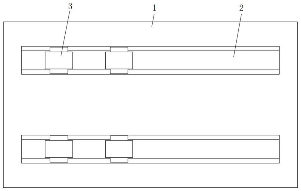
[0039] Such as image 3 As shown, this embodiment is basically the same as Embodiment 1. Preferably, the cross-sections of the installation groove-2 and the installation block-3 are arranged in the shape of a "cross", and there are two installation blocks-3.

[0040] In this embodiment, two installation blocks one 3 are arranged in the installation groove one 2, so that the fixing of the working disk 4 is more stable.


PUM


Abstract

The invention discloses efficient drilling equipment for brush plate machining. The equipment comprises a workbench, first mounting grooves are formed in the front side and the rear side of the top face of the workbench in a penetrating mode, first mounting blocks are slidably connected to the inner walls of the first mounting grooves, a working disc is fixedly connected to the top faces of the four first mounting blocks through screws, a fixing groove is formed in the top face of the working disc, first electric telescopic rods are fixedly connected to the side walls of the fixing groove through screws, extrusion blocks are fixedly connected to the output ends of the first electric telescopic rods through screws, a toothed bar is further fixedly connected between the bottom faces of the two first mounting blocks at the front end and the rear end, a driving mechanism is further arranged on the lower side of the middle of the workbench, and a mounting frame is further fixed to the middle of the top face of the workbench. The efficient drilling equipment is reasonable in design and stable in device operation; synchronous drilling operation of a plurality of bristle planting holes can be completed at a time, so that the working efficiency of brush plate drilling machining is greatly improved; and the bristle planting holes at different intervals are convenient to adjust during drilling, and then the application range of the device is greatly widened.

Description

technical field [0001] The invention relates to the technical field of brush plate processing equipment, in particular to a high-efficiency drilling equipment for brush plate processing. Background technique [0002] The product made of hair-planting on a specific board is called a brush board. Before the hair-planting, it is necessary to drill the hair-planting holes on the surface of the brush board, which requires the use of a drilling device. [0003] After searching, the patent application number 201922039885.7 discloses a high-efficiency and precise drilling machine for brush board processing, including a base, two symmetrical uprights are fixedly installed on the left and right sides of the base, and the tops of the two uprights are A top block is fixedly installed between them, and a groove is provided inside the top block, and a first bearing seat and a second bearing seat are arranged in the groove, and the inner ring of the first bearing seat is rotatably connecte...

Claims


Application Information

Patent Timeline
Patent Type & Authority Applications(China)
IPC IPC(8): A46D3/02A46D3/08
CPCA46D3/02A46D3/085A46D3/08A46D3/087
Inventor 胡爽徐东海徐小祥
Owner 安徽三和刷业股份有限公司
Why Eureka
Try Eureka