Assembly type special rail connecting structure and using method thereof

A rail connection and assembly technology, applied in the direction of rails, rail joints, roads, etc., to achieve the effect of increasing compressive resistance and structural strength, increasing functionality, and prolonging service life

Inactive Publication Date: 2021-06-25
温州方舵建筑有限公司
View PDF0 Cites 0 Cited by
  • Summary
  • Abstract
  • Description
  • Claims
  • Application Information

AI Technical Summary

Problems solved by technology

[0004] The purpose of the present invention is to provide an assembled special track connection structure and its use method to solve the related problems raised in the above-mentioned background technology

Method used


Image

  • Assembly type special rail connecting structure and using method thereof
  • Assembly type special rail connecting structure and using method thereof
  • Assembly type special rail connecting structure and using method thereof

Examples


Embodiment 1

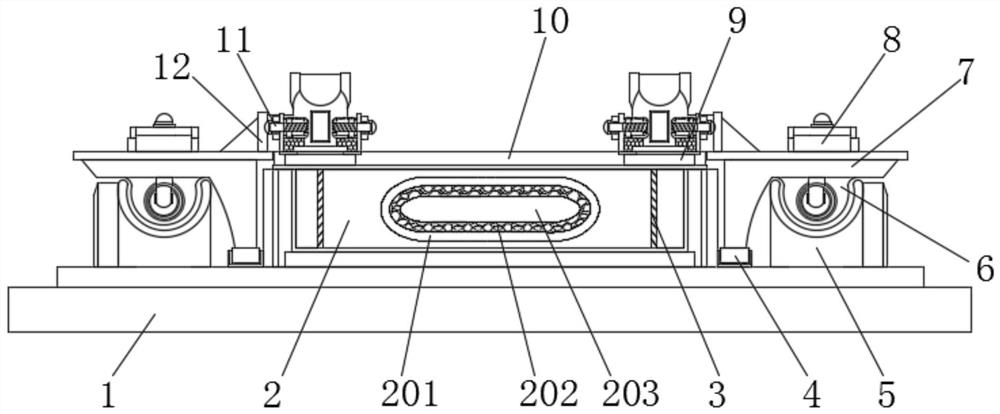
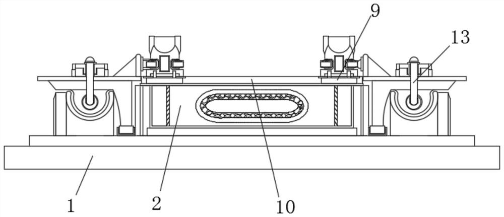
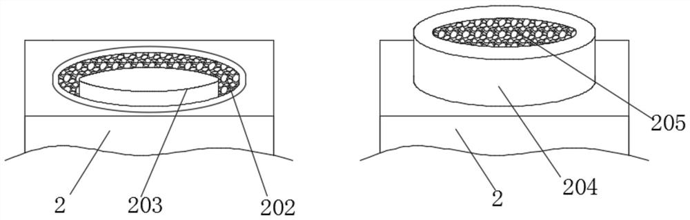
[0035] see Figure 1-7 , the present invention provides a technical solution: an assembled special track connection structure, including a prefabricated base 1, a pressure-bearing groove 2 is provided at the middle position of the top of the prefabricated base 1, and a pressure-bearing groove 2 is provided inside the pressure-bearing groove 2. Buffer assembly, the two sides of the top of the prefabricated base 1 are provided with semi-arc-shaped slide grooves 5, the bottom of both sides of the pressure-bearing groove 2 is provided with guide grooves 4, and the inner sides of the two sets of guide grooves 4 are provided with mutually matching mounting brackets 7, The sides of the bottoms of the two groups of mounting frames 7 that are far away from each other are provided with arc-shaped sliding sleeves 6 that are compatible with the semi-arc-shaped chute 5, and the tops of the two groups of mounting frames 7 are provided with engaging blocks 8, and the two groups of arc-shaped ...

Embodiment 2

[0042] see Figure 1-7 , the present invention provides a technical solution: an assembled special track connection structure, including a prefabricated base 1, a pressure-bearing groove 2 is provided at the middle position of the top of the prefabricated base 1, and a pressure-bearing groove 2 is provided inside the pressure-bearing groove 2. Buffer assembly, the two sides of the top of the prefabricated base 1 are provided with semi-arc-shaped slide grooves 5, the bottom of both sides of the pressure-bearing groove 2 is provided with guide grooves 4, and the inner sides of the two sets of guide grooves 4 are provided with mutually matching mounting brackets 7, The sides of the bottoms of the two groups of mounting frames 7 that are far away from each other are provided with arc-shaped sliding sleeves 6 that are compatible with the semi-arc-shaped chute 5, and the tops of the two groups of mounting frames 7 are provided with engaging blocks 8, and the two groups of arc-shaped ...


PUM


Abstract

The invention discloses an assembly type special rail connecting structure and a using method thereof. The assembly type special rail connecting structure comprises a prefabricated base, a pressure bearing groove is formed in the middle of the top of the prefabricated base, a pressed buffering assembly is arranged in the pressure bearing groove, semi-arc-shaped sliding grooves are formed in the two sides of the top of the prefabricated base, and guide grooves are formed in the bottoms of the two sides of the pressure bearing groove. Mounting frames matched with each other are arranged on the inner sides of the two groups of guide grooves. Through mutual cooperation of the track butt-joint assemblies, the butt-joint channels and the U-shaped grooves formed in the two ends of the track plate can form structural adaptation, the butt-joint channels are blocked by the reinforcing plates after being inserted into the U-shaped grooves to form a whole, meanwhile, the stability of assembly and connection of the butt-joint channels is provided under the pressure of the elastic pieces, and the stability of assembly and connection of the butt-joint channels is improved. According to the device, the connecting structure is prevented from generating certain position deviation during fixing, and the rail bolts penetrate through the threaded holes to be in threaded fit with the nut grooves, so that the two groups of device bodies can be quickly butted and fixed, and subsequent disassembly and maintenance work is facilitated.

Description

technical field [0001] The invention relates to the technical field of assembled rails, in particular to an assembled special rail connection structure and a method for using the same. Background technique [0002] In recent years, my country's urban rail transit construction has developed rapidly. As a track structure that guides the operation of rolling stock, directly bears the load from the train, and transmits the load to the roadbed or bridge and tunnel structures, it is a very important part of urban rail transit; [0003] When the current prefabricated rails are docked, the joints are often aligned and connected through the external docking plate. However, this method not only makes the seams of the rails prone to breakage and position deviation, but also easily causes the rails to fail to operate normally. During the follow-up maintenance and disassembly, the external fixing plate is not convenient for quick disassembly and assembly, which makes the operation more ...

Claims


Application Information

Patent Timeline
Patent Type & Authority Applications(China)
IPC IPC(8): E01B11/00E01B19/00
CPCE01B11/00E01B19/00
Inventor 王凯
Owner 温州方舵建筑有限公司
Why Eureka
Try Eureka