A mine-used built-in piston mechanical claw

A technology of piston type and mechanical claws, which is applied in the field of built-in piston type mechanical claws for mining, can solve the problems of large pick-up space for drill pipes, and achieve the effects of compact pick-up structure design, saving transposition space, and precise control

Active Publication Date: 2022-04-22
CHINA COAL TECH & ENG GRP CHONGQING RES INST CO LTD
View PDF9 Cites 0 Cited by
  • Summary
  • Abstract
  • Description
  • Claims
  • Application Information

AI Technical Summary

Problems solved by technology

[0003] In view of this, the purpose of this application is to provide a mine-used built-in piston-type mechanical claw, so that the clamping power of the mechanical claw is parallel to the axis of the drill pipe, and solve the problem of drilling due to the fact that the clamping power of the mechanical claw is perpendicular to the axis of the drill pipe. Problem with large rod pickup space

Method used


Image

  • A mine-used built-in piston mechanical claw
  • A mine-used built-in piston mechanical claw
  • A mine-used built-in piston mechanical claw

Examples


Embodiment

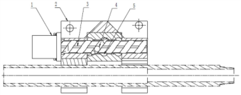
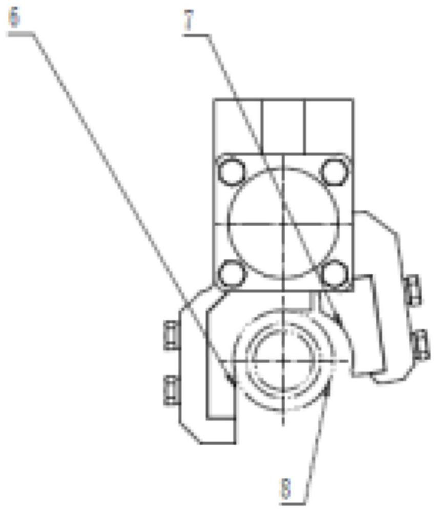
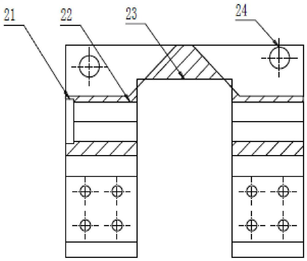
[0038] A mine piston type mechanical claw, such as Figure 1 to Figure 7 As shown, it includes a fixed claw 2, a movable claw 5, a telescopic shaft 3, a ball, a ball fixing frame and a driving device 1, and the driving device 1 drives the telescopic shaft 3 to move along the guide hole 22 provided on the fixed claw 2, and passes through the ball. The movement converts the thrust of the driving device into the clamping force of the movable jaw. The relative installation position and specific structure and function of each component are as follows:

[0039] Driving device 1: a hydraulic cylinder, parallel to the axis of the drill pipe 8, providing clamping power, installed at one end of the fixed claw 2, the piston of the hydraulic cylinder is connected with the telescopic shaft 3, and drives the telescopic shaft 3 to guide the hexagonal direction of the fixed claw 2 Axial movement in the hole.

[0040]Fixed claw 2: One end of the fixed claw 2 is connected with the hydraulic cy...


PUM


Abstract

The invention relates to a mine-used built-in piston-type mechanical claw, which belongs to the technical field of coal mine drilling rigs, and includes a fixed claw, which is provided with a guide hole along its length direction, and a telescopic shaft with only an axial movement degree of freedom is arranged in the guide hole. One end of the telescopic shaft is connected with a driving device capable of driving along its axial movement; the telescopic shaft is also set with a movable claw that can rotate around its axis, and the movable claw and the fixed claw form a clamping center parallel to the telescopic shaft jaws. The clamping power of the mechanical claws of the present invention is parallel to the axis of the drill pipe, which solves the problem of large pick-up space for the drill pipe caused by the clamping power of the mechanical claws being perpendicular to the axis of the drill pipe.

Description

technical field [0001] The invention belongs to the technical field of coal mine drilling rigs, and relates to a mine-used built-in piston mechanical claw. Background technique [0002] With the development of intelligent mining in coal mines, the development of automatic drilling rigs is in the ascendant. At present, the mechanical claw adopts external load, and the power direction is parallel to the clamping load and perpendicular to the axis of the drill pipe, so that the pick-up space of the drill pipe is large, the direction of the downhole space is obvious, the space in the direction of the rack axis is relatively sufficient, and the longitudinal space is relatively insufficient. Due to the inconsistency between the structure of the mechanical claw and the directionality of the underground space, the development of the automatic drilling rig to both ends is limited, so that the drilling rig cannot meet the drilling needs of small mines and large mines. Contents of th...

Claims


Application Information

Patent Timeline
Patent Type & Authority Patents(China)
IPC IPC(8): B25J15/00
CPCB25J15/00
Inventor 李学忠陈航辛德忠王清峰万军蒲剑刘小华吕晋军杨林邱响林马振纲王志锦唐敏杜渔舟雷万年周富佳李淑健
Owner CHINA COAL TECH & ENG GRP CHONGQING RES INST CO LTD
Why Eureka
Try Eureka