
Rotary table

A technology of turntable and swivel seat, which is applied in the direction of large fixed members, metal processing machinery parts, metal processing equipment, etc., can solve the problems of low processing efficiency, slow processing speed, and inability to meet processing needs, so as to reduce multiple disassembly and improve The effect of processing efficiency and processing speed

Pending Publication Date: 2021-06-25
深圳市润鑫鸿五金塑胶制品有限公司
View PDF0 Cites 0 Cited by
  • Summary
  • Abstract
  • Description
  • Claims
  • Application Information

AI Technical Summary

Problems solved by technology

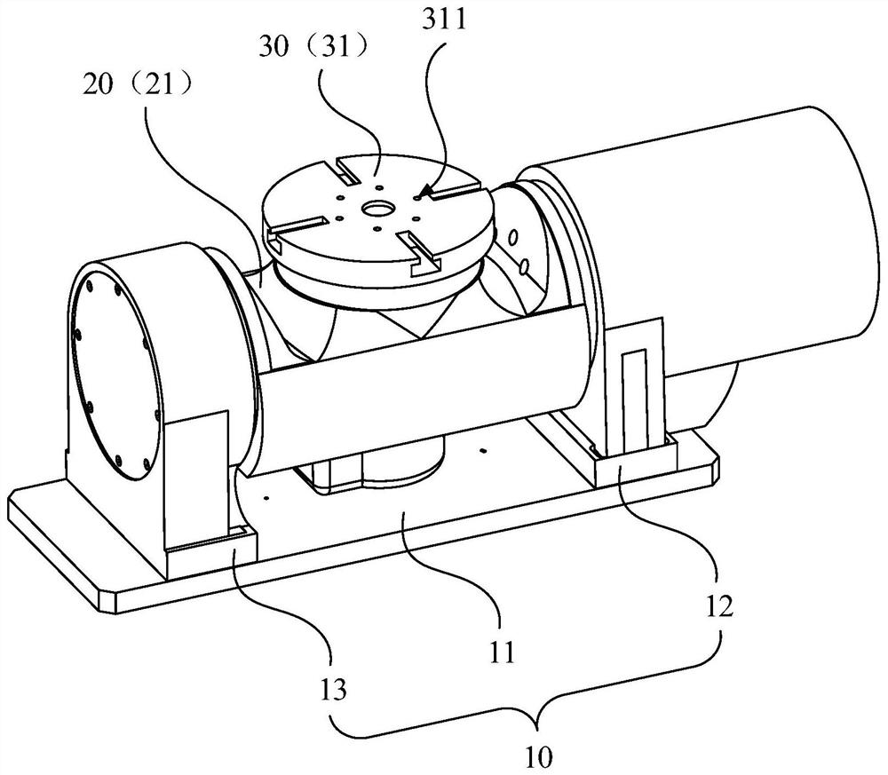
[0004] The main purpose of the present invention is to provide a turntable that can rotate at multiple angles to process the workpiece at different angles, aiming at solving the problem that the existing turntable cannot meet the processing requirements of the current workpiece, the processing efficiency is low, and the processing speed is slow The problem

Method used


Image

  • Rotary table
  • Rotary table
  • Rotary table

Examples


Embodiment Construction

[0030] In order to understand the above-mentioned purpose, features and advantages of the present invention more clearly, the present invention will be further described in detail below in conjunction with the accompanying drawings and specific embodiments. It should be noted that, in the case of no conflict, the embodiments of the present application and the features in the embodiments can be combined with each other.

[0031] In the description of the present invention, it should be noted that the orientation or positional relationship indicated by the terms "upper", "lower", etc. is based on the orientation or positional relationship shown in the drawings, and is only for the convenience of describing the present invention and simplifying the description. It is not intended to indicate or imply that the referred device or element must have a particular orientation, be constructed in a particular orientation, and operate in a particular orientation, and thus should not be con...


PUM


Abstract

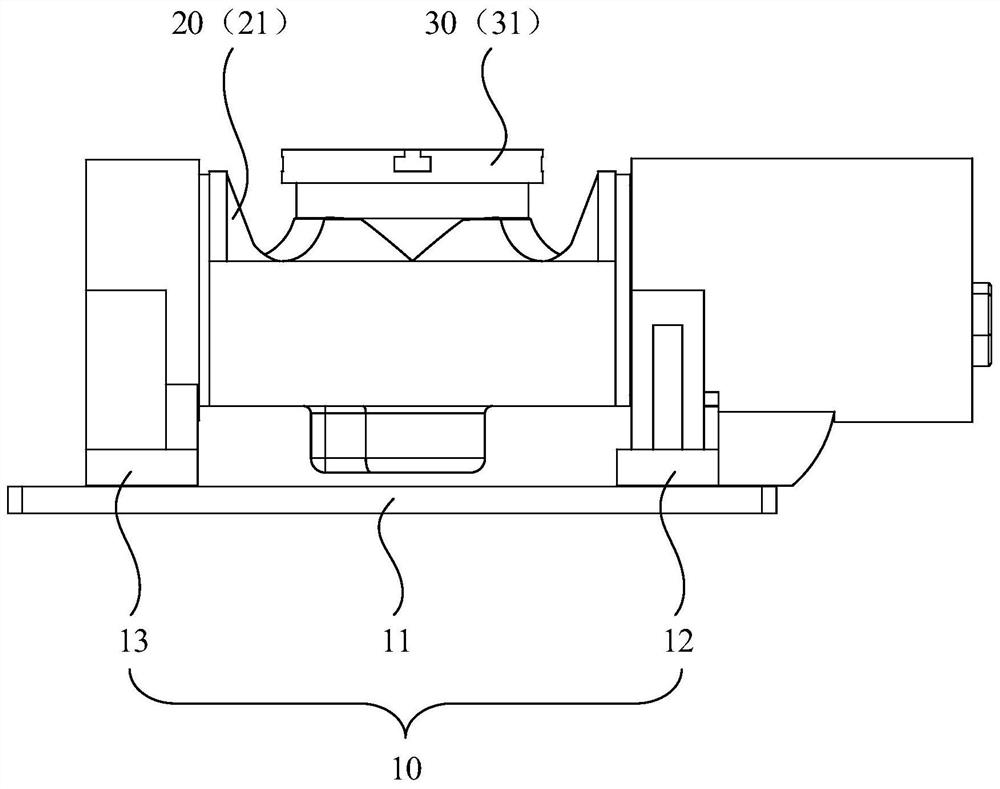
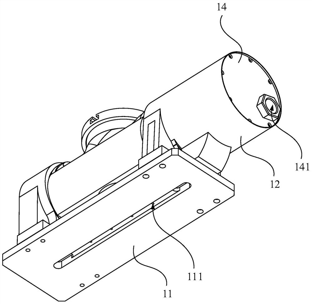
The invention relates to the technical field of machining equipment, and particularly relates to a rotary table. The rotary table comprises a base, a first rotating assembly and a second rotating assembly; the first rotating assembly is fixed to the base and comprises a rotating seat capable of rotating around a first rotating axis relative to the base; the second rotating assembly is fixed to the rotating seat and comprises a fixing table capable of rotating around a second rotating axis relative to the rotating seat, and the fixing table is used for fixing a to-be-machined workpiece; and the second rotating axis is perpendicular to the first rotating axis. Due to the fact that the rotating seat can rotate around the first rotating axis and meanwhile drives the fixing table to rotate around the first rotating axis, and the fixing table can rotate around the second rotating axis, the degree of freedom of the rotary table is high, the to-be-machined workpiece can rotate by multiple angles after being fixed, and therefore the to-be-machined workpiece can be machined by different angles conveniently, the machining requirements of various workpieces at present are met, and repeated dismounting of the to-be-machined workpiece can be reduced.

Description

technical field [0001] The invention relates to the technical field of machining equipment, in particular to a turntable. Background technique [0002] During the machining process, it is necessary to use a turntable to fix the workpiece to be processed so that it occupies the correct position for processing. Nowadays, with the rapid development of workpiece manufacturing technology, the shape of the workpiece is becoming more and more complex, the processing requirements of the workpiece are getting higher and higher, and higher requirements are put forward for the turntable, especially for some special-shaped workpieces. [0003] However, the turntables of existing CNC machine tools are generally fixed or rotating. During machining, the machining angle of the workpiece to be processed is usually limited and the degree of freedom is not enough, resulting in that some parts of the workpiece to be processed cannot be processed. It cannot meet the processing needs of the curr...

Claims


Application Information

Patent Timeline
IPC IPC(8): B23Q1/25
CPCB23Q1/25
Inventor 章俊黄桂枝
Owner 深圳市润鑫鸿五金塑胶制品有限公司
Learn More