
Ointment smearing device for dermatology department

A dermatology and ointment technology, applied in the field of smearing devices, can solve the problems of uneven smearing, poor smearing effect, easy to cause infection, etc., and achieve the effects of accurate cutting position, improved efficiency, and improved operation convenience.

Active Publication Date: 2021-06-25
翁鹏
View PDF0 Cites 0 Cited by
  • Summary
  • Abstract
  • Description
  • Claims
  • Application Information

AI Technical Summary

Problems solved by technology

[0002] Existing dermatological ointment application devices not only consume more medication, but also apply unevenly and have poor application effects, and most of them cannot increase the speed at which the patient's skin absorbs the ointment, which is not conducive to improving the speed of drug effect and cannot shorten the time for patients to take effect. In addition, most of the existing dermatological ointment applicators are made of common materials, which are easy to breed bacteria, poor hygienic conditions, and poor safety performance
And if you apply it with your hands, it is easy to cause infection

Method used


Image

  • Ointment smearing device for dermatology department
  • Ointment smearing device for dermatology department
  • Ointment smearing device for dermatology department

Examples


Embodiment 1

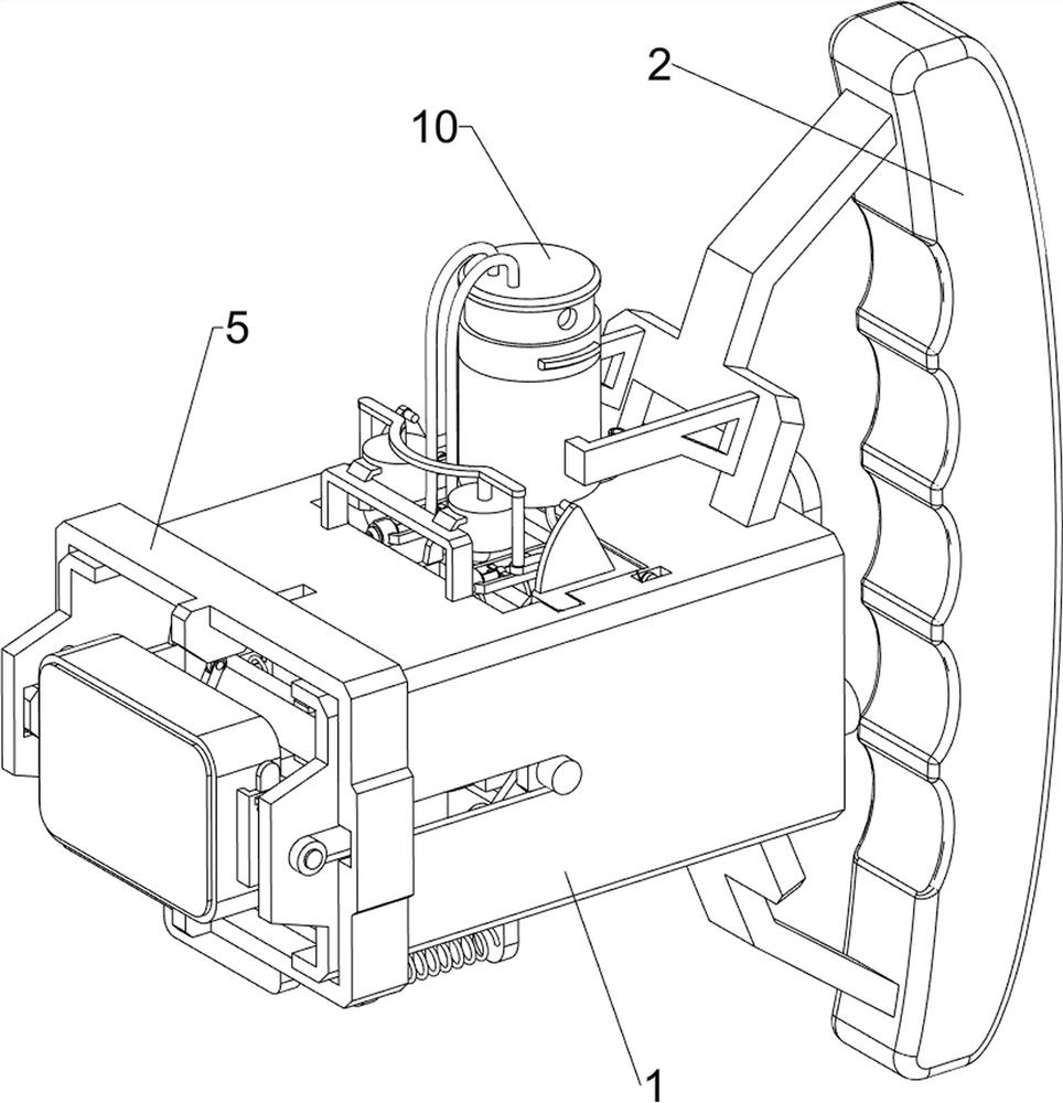
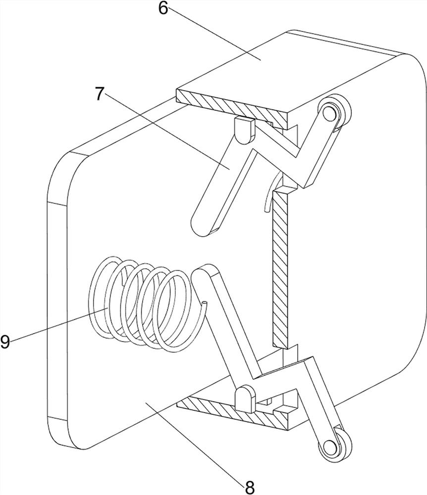
[0034] A dermatology ointment applicator, such as Figure 1-8 As shown, it includes a casing 1, a handle 2, a turning assembly 3, a moving assembly 4, a movable assembly 5, a box body 6, a special-shaped rod 7, a movable plate 8 and a sixth spring 9, and the right side of the casing 1 is provided with a handle 2 , the left side of the housing 1 is provided with an overturning assembly 3, the interior of the housing 1 is provided with a moving assembly 4, the left side of the housing 1 is provided with a movable assembly 5, the left side of the overturning assembly 3 is provided with a box body 6, and the middle part of the inner side of the box body 6 The up and down symmetrical rotation type is provided with a special-shaped rod 7, and the left side of the box body 6 is provided with a movable plate 8. The movable plate 8 and the special-shaped rod 7 cooperate with each other, and a sixth spring is symmetrically connected between the movable plate 8 and the box body 6. 9.

...

Embodiment 2

[0040] On the basis of Example 1, such as Figure 9-15 As shown, a blanking assembly 10 is also included, and the blanking assembly 10 includes a cylinder body 1001, a sealing ring 1002, a feed pipe 1003, a discharge pipe 1004, an N-shaped rod 1005, a piston barrel 1006, a piston frame 1007, a seventh Spring 1008, air inlet pipe 1009, air outlet pipe 1010 and sealing plug 1011, cylinder body 1001 is provided on the left side of the handle 2, sealing ring 1002 is provided slidingly on the upper side of cylinder body 1001, and feeding pipe 1003 is provided on the right side of the lower part of cylinder body 1001 , the bottom of the cylinder 1001 is symmetrically provided with a discharge pipe 1004, the top of the housing 1 is provided with an N-shaped rod 1005, and the upper part of the N-shaped rod 1005 is provided with a piston cylinder 1006 symmetrically front and rear, and a piston is provided slidingly between the upper sides of the piston cylinder 1006. The frame 1007, th...


PUM


Abstract

The invention relates to a smearing device, in particular to an ointment smearing device for the dermatology department. The ointment smearing device for the dermatology department aims at achieving the technical effects that smearing is uniform, the smearing effect is good, and operation is convenient. According to the technical scheme, the ointment smearing device for the dermatological department comprises a shell, a handle arranged on one side of the shell, an overturning assembly arranged on one side in the shell; a moving assembly arranged in the shell; and a movable assembly arranged on one side of the shell. When people move a piston frame downwards, the piston frame enables air in a piston barrel to enter a barrel body through an air outlet pipe, due to the fact that the barrel body is located in a closed space, a sealing plug can move downwards, the sealing plug can drive ointment to move downwards to be extruded to a movable plate through a discharging pipe, and people can conduct feeding work more conveniently.

Description

technical field [0001] The invention relates to a smearing device, in particular to a dermatology ointment smearing device. Background technique [0002] Existing dermatological ointment application devices not only consume more medication, but also apply unevenly and have poor application effects, and most of them cannot increase the speed at which the patient's skin absorbs the ointment, which is not conducive to improving the speed of drug effect and cannot shorten the time for patients to take effect. In addition, most of the existing dermatological ointment applicators are made of common materials, which are easy to nourish bacteria, have poor hygienic conditions and poor safety performance. And smearing with hands can easily cause infection. [0003] Therefore, it is urgent to propose a dermatology ointment applicator that is more uniform in smearing, better in smearing effect and easy to operate. Contents of the invention [0004] In order to overcome poor sanitar...

Claims


Application Information

Patent Timeline
IPC IPC(8): A61M35/00
CPCA61M35/003A61M2210/04A61M2210/00
Inventor 邓顺琴
Owner 翁鹏
Learn More