
Positioning device for fiber-optic gyroscope inclinometer and positioning method thereof

A technology of fiber optic gyroscope and positioning device, which is applied in the directions of surveying, earthwork drilling, wellbore/well components, etc. It can solve the problems of inaccurate data and achieve the effects of improving accuracy, facilitating data collection, stable rotation and precision

Inactive Publication Date: 2021-06-22
刘铭
View PDF1 Cites 0 Cited by
  • Summary
  • Abstract
  • Description
  • Claims
  • Application Information

AI Technical Summary

Problems solved by technology

[0004] The above-mentioned patents have the following disadvantages: the main accuracy of the inclinometer is determined by the two parts of rotation and positioning, and the above-mentioned assembly relies on the rotation of the positioning shaft to drive the rotation of the inclinometer, and its positioning shaft is directly connected to the motor, regardless of whether it is welded , coupling connection or flange connection, the wear of any part in the entire rotating transmission chain will directly cause inaccurate data such as coaxiality and rotation angle, so further improvement is needed

Method used


Image

  • Positioning device for fiber-optic gyroscope inclinometer and positioning method thereof
  • Positioning device for fiber-optic gyroscope inclinometer and positioning method thereof
  • Positioning device for fiber-optic gyroscope inclinometer and positioning method thereof

Examples


Embodiment 1

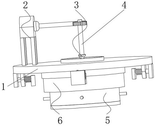
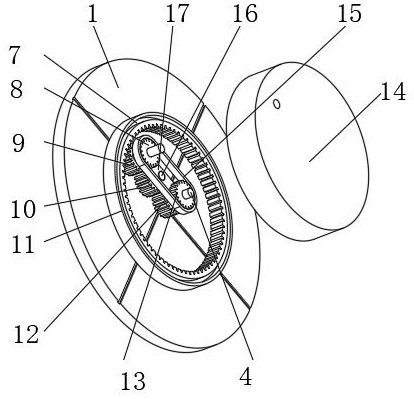
[0039] A positioning device for a fiber optic gyro inclinometer, such as figure 2 As shown, it includes a support base 1, the inner wall of the support base 1 is rotatably connected with a main shaft 4, and the bottom of the main shaft 4 is provided with a precision rotation transmission assembly 6, and the precision rotation transmission assembly 6 includes an inner gear ring 11 and a direct swivel ring 14 , the inner toothed ring 11 is slidably connected with the direct swivel 14 through the chute one 7 provided therein, the bottom outer wall of the main shaft 4 is connected with a spur gear three 12 and a sprocket two 13 through a key, and the spur gear three 12 One side outer wall is engaged with spur gear two 10, and the other side outer wall of spur gear two 10 is engaged with spur gear one 9, and the outer wall of spur gear one 9 is meshed with the inner wall of inner gear ring 11, and described spur gear one 9 and spur gear Two 10 are connected with the same connecting ...

Embodiment 2

[0044] A positioning device for a fiber optic gyro inclinometer, such as figure 1 , 5 , 6, in order to solve the coaxiality problem of the inclinometer and the device; the present embodiment makes the following improvements on the basis of embodiment 1: the bottom outer wall of the direct swivel 14 is provided with a coaxial fixing assembly 5, so The coaxial fixing assembly 5 includes an outer fixing ring 35 and a fastening ring 38, the outer fixing ring 35 is rotatably connected with the fixing ring 38, and the inner wall of the outer fixing ring 35 is threaded with four circular arrays of screws 37. The outer wall of the screw rod 37 located at the inside of the outer fixing ring 35 is rotatably connected with a claw plate 34, and the claw plate 34 is slidably connected with the outer fixing ring 35 through a slide bar 2 36. The outer wall of the screw rod 37 is connected with a fastening gear 39 through a key, The four fastening gears 39 are all meshed with the fastening r...

Embodiment 3

[0047] A positioning method for a positioning device used in an optical fiber gyroscope inclinometer, the specific steps are as follows:

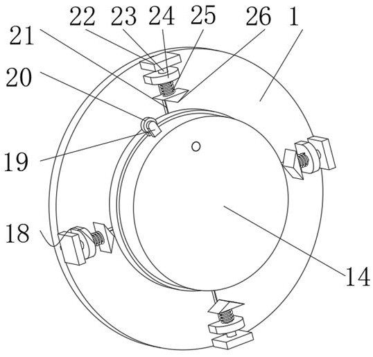
[0048] S1: Determine the positions of the four sets of positioning components 18 according to the positions of the two indexing lines 21;

[0049] S2: Place the inclinometer between the four claw plates 34, and twist the fastening ring 38 to clamp it coaxially;

[0050] S3: Start the motor 28 subsequently, which can drive the direct swivel 14, the entire coaxial fixed assembly 5, and the inclinometer to rotate through the transmission chain. When rotating to one of the positioning assemblies 18, record the position and record the position as zero point;

[0051] S4: Continuously start the motor 28, and then pass through four sets of positioning components 18 in sequence to realize reliable positioning of 0°-90°-180°-270°-360°.

[0052] Working principle: when the fastening ring 38 rotates, it drives the four fastening gears 39 to rotate t...


PUM


Abstract

The invention discloses a positioning device for a fiber-optic gyroscope inclinometer and a positioning method thereof, and relates to the technical field of fiber-optic gyroscope inclinometers. The problem of rotation angle precision is solved. The device comprises a supporting seat, wherein the inner wall of the supporting seat is rotationally connected with a main shaft, the bottom of the main shaft is provided with an accurate rotating transmission assembly, and the accurate rotating transmission assembly comprises an inner gear ring and a direct rotating ring. The method specifically comprises the steps that the positions of four sets of positioning assemblies are determined according to the positions of two indexing lines; and the inclinometer is placed among four claw plates, a fastening ring is screwed, and the inclinometer is coaxially clamped. According to the positioning device, two driving chains exist to form a complete transmission closed chain, so that the transmission is more stable, and the two transmission chains have different transmission forms and different actual wear positions, so that even if wear occurs, complementation can be realized through the two transmission chains, and the rotation of the inclinometer on the direct rotating ring is more stable and accurate.

Description

technical field [0001] The invention relates to the technical field of fiber optic gyro inclinometers, in particular to a positioning device and a positioning method for fiber optic gyro inclinometers. Background technique [0002] In the development of new oil wells, fiber optic gyro inclinometers are generally used to measure the angle of oil wells for directional production. When the fiber optic gyro inclinometers measure the angles of oil wells, they need to be used with positioning devices. The positioning devices need to realize the inclinometer Rotation function, and when rotating, accurate positioning must be carried out at the positions of 0 degrees, 90 degrees, 180 degrees, 270 degrees and 360 degrees of rotation, so as to ensure the required data of the inclinometer to measure the angle of the oil well. [0003] After retrieval, the Chinese Patent Publication No. is CN203603883U, which discloses a fiber optic gyro inclinometer positioning device, including a posit...

Claims


Application Information

Patent Timeline
Patent Type & Authority Applications(China)
IPC IPC(8): E21B47/022
CPCE21B47/022
Inventor 刘铭
Owner 刘铭
Learn More