High density connector receptacle

A technology of sockets and contacts, applied in the direction of contact parts, etc., can solve problems such as difficulties in socket contacts

Inactive Publication Date: 2003-12-03
ELCO
View PDF9 Cites 0 Cited by
  • Summary
  • Abstract
  • Description
  • Claims
  • Application Information

AI Technical Summary

Problems solved by technology

Since the above-mentioned connectors tend to be more and more miniaturized, which involves a decrease in the center-to-center distance of adjacent socket contacts, to improve the automation of the above-mentioned manufacturing process, the width of each unformed socket contact should not be greater than the manufactured one. The center-to-center distance between a row of socket contacts makes it increasingly difficult to make functionally desirable socket contacts using this stamping process

Method used


Image

  • High density connector receptacle
  • High density connector receptacle

Examples


Embodiment Construction

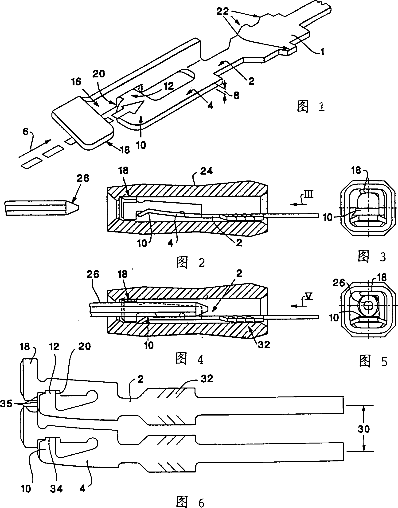
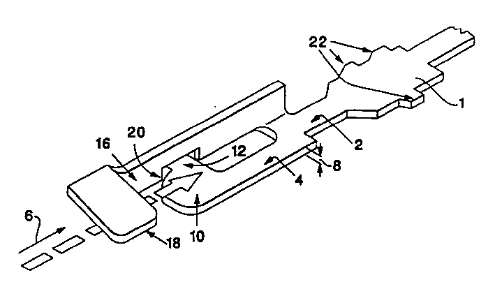
[0018] Figure 1 shows a preferred embodiment of the socket contact of the present invention. When making the contact, first punch out a plurality of such contact patterns on a flat metal blank, such as an elastic metal sheet, and then bend several parts of the contact blank to form a structure as shown in the figure contacts.

[0019] The socket contact includes: a main body 1 , a first contact arm 2 and a second contact arm 4 . The two contact arms extend along the pin insertion direction 6 and adjoin each other front and back. Each contact arm 2 and 4 is located on the socket contact, and the thickness direction 8 of the contact is perpendicular to the insertion direction 6 of the pin, and parallel to the first direction of the bending direction of the two contact arms when the pin is inserted. In a second direction perpendicular to said insertion direction and the first direction, the contact arm 2 is narrower than the dimensions of the main body part 1 and the contact ar...


PUM


Abstract

An electrical socket contact which is connectable to a pin contact by insertion movement of the pin contact into the socket contact in an insertion direction. The socket contact includes: a body portion having elements for securing the socket contact in a receptacle housing so that the body portion is fixed in position in the receptacle; a first beam cantilevered to the body portion; a second beam having a proximal end cantilevered to the first beam and having a distal end spaced a distance from the first beam in a direction away from the first beam and parallel to the insertion direction; a first contact element located at the distal end of the second beam; a support arm secured to the proximal end of the second beam and having a distal end spaced a distance from the proximal end of the second beam in a direction away from the first beam and parallel to the insertion direction; and a second contact element located at the distal end of the support arm. The first and second beams are both flexible in a first direction transverse to the insertion direction and, during insertion of a contact pin into the socket, the pin moves the contact elements away from one another in the first direction.

Description

technical field [0001] The present invention relates to receptacle contacts which can be arranged in a housing with close spacing between the contacts for connection with a corresponding set of conductive pins inserted therebetween to form a connector. This type of connector is typically used on electronic equipment such as computers. Background technique [0002] In order for this type of connector to perform its intended function well, the basic conditions that must be met are as follows: the force required to insert the pin into the socket contact, that is, the insertion force must be small enough to avoid damage during the insertion process. Deflect the pins; when designing a socket contact, it is necessary to ensure that it has a suitable contact pressure with the pins, and to allow a certain degree of deviation in the posture of each pin. [0003] When manufacturing receptacle contacts, generally, a metal sheet is first stamped into a carrier bar, and the carrier bar ...

Claims


Application Information

Patent Timeline
IPC IPC(8): H01R13/11
CPCH01R13/11
Inventor 史蒂文·费尔德曼
Owner ELCO
Why Eureka
Try Eureka