
Microphone and its manufacturing method

A manufacturing method and microphone technology, applied in the direction of sensors, electrostatic transducer microphones, electrical components, etc., can solve the problems of inability to ensure the consistency of the lateral etching depth of the substrate 100, remaining sacrificial layers, and the lateral etching depth is not fixed, etc., Achieve the effect of improving mechanical reliability, reducing restrictions and improving performance

Active Publication Date: 2021-08-13
SEMICON MFG ELECTRONICS (SHAOXING) CORP
View PDF5 Cites 0 Cited by
  • Summary
  • Abstract
  • Description
  • Claims
  • Application Information

AI Technical Summary

Problems solved by technology

[0005] 1. During the process of wet etching the sacrificial layer 102, the wet etching will laterally etch to both sides of the cavity 106 (also called lateral etching), and the wet etching uses Factors such as the newness of the etchant and the etching time will affect the extent of the lateral etching, resulting in that the wet etching cannot guarantee the consistency of the lateral etching depth at different positions of the substrate 100 (ie, the wafer). Consistency, that is, the lateral etching depth (ie, the undercut distance) on the substrate 100 (ie, the wafer) is not constant when wet etching removes the excess sacrificial layer
[0006] 2. If the wet etching time is shortened to reduce the degree of lateral etching, it will cause the problem that the sacrificial layer 102 remains on the diaphragm 101 or the etching stop layer 103

Method used


Image

  • Microphone and its manufacturing method
  • Microphone and its manufacturing method
  • Microphone and its manufacturing method

Examples


Embodiment Construction

[0034] In the following description, numerous specific details are given in order to provide a more thorough understanding of the present invention. It will be apparent, however, to one skilled in the art that the present invention may be practiced without one or more of these details. In other examples, some technical features known in the art are not described in order to avoid confusion with the present invention. It should be understood that the invention can be embodied in different forms and should not be construed as limited to the embodiments set forth herein. Rather, these embodiments are provided so that this disclosure will be thorough and complete, and will fully convey the scope of the invention to those skilled in the art. In the drawings, the size and relative sizes of layers and regions may be exaggerated for clarity. Like reference numerals refer to like elements throughout. It will be understood that when an element or layer is referred to as being "on" or...


PUM


Abstract

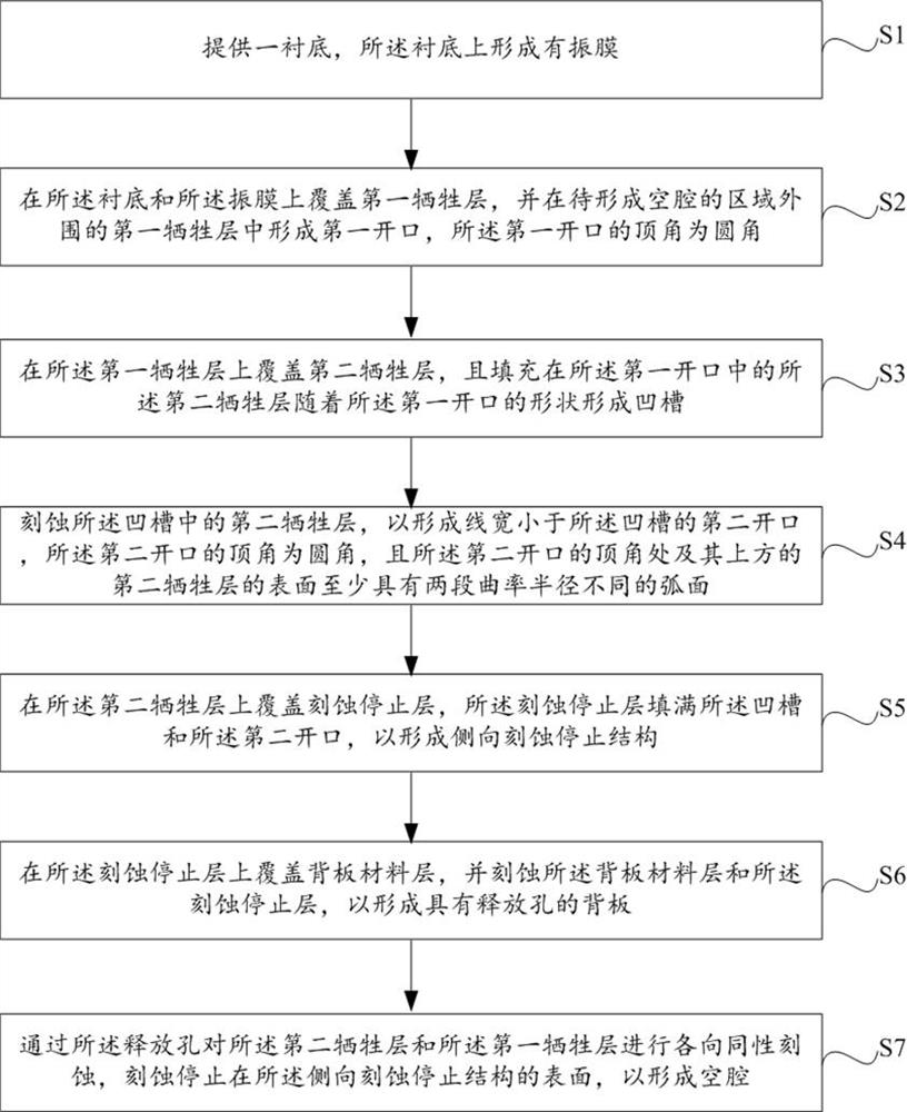
The present invention provides a microphone and its manufacturing method. Because the first opening of the first sacrificial layer makes the second sacrificial layer conformally form a groove, and then forms the second opening in the groove, then the second opening can be The etch stop layer is filled in the middle to form a lateral stop structure, whereby the first sacrificial layer and the second sacrificial layer are isotropically etched through the release hole to form the diaphragm and the back plate of the microphone. When the cavity is hollow, the etching can be stopped on the surface of the lateral stop structure, which realizes the effect of controllable undercut distance between the first sacrificial layer and the second sacrificial layer, and reduces the limitation on the isotropic etching process. After the cavity is formed, a more stable support column can be formed, which improves the mechanical reliability of the microphone.

Description

technical field [0001] The invention relates to the technical field of semiconductor device manufacturing, in particular to a microphone and a manufacturing method thereof. Background technique [0002] Condenser microphones are widely used because of their characteristics such as wide frequency response, ultra-high sensitivity, ultra-fast instantaneous response speed, ultra-low touch noise, drop resistance and impact resistance. Condenser microphones usually have two polar plates, which are called the diaphragm and the back plate respectively. There is a cavity between the diaphragm and the back plate, and the sound causes the diaphragm to vibrate, thereby realizing sound recording. [0003] Currently, during the manufacturing process of condenser microphones, please refer to figure 1 As shown, the cavity 106 is usually manufactured between the diaphragm 101 and the back plate 104 by means of the sacrificial layer 102. The specific process includes: first growing silicon o...

Claims


Application Information

Patent Timeline
Patent Type & Authority Patents(China)
IPC IPC(8): H04R31/00H04R19/00H04R19/04
CPCH04R19/005H04R19/04H04R31/00
Inventor 傅思宇谢志平闾新明
Owner SEMICON MFG ELECTRONICS (SHAOXING) CORP
Learn More