Rotating motor
A technology for rotating electrical machines and rotating directions, which is applied in the direction of electromechanical devices, electrical components, electric components, etc., and can solve problems such as the decline in efficiency of rotating machines and the increase in high-frequency components of rotor magnetomotive force, so as to reduce high-frequency iron loss and improve efficiency , the effect of suppressing high-frequency components
- Summary
- Abstract
- Description
- Claims
- Application Information
AI Technical Summary
Problems solved by technology
Method used
Image
Examples
Embodiment approach 1
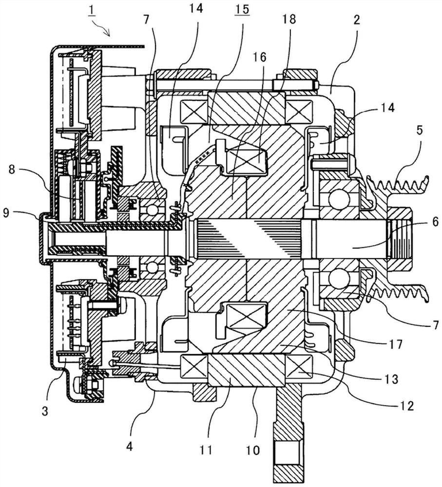
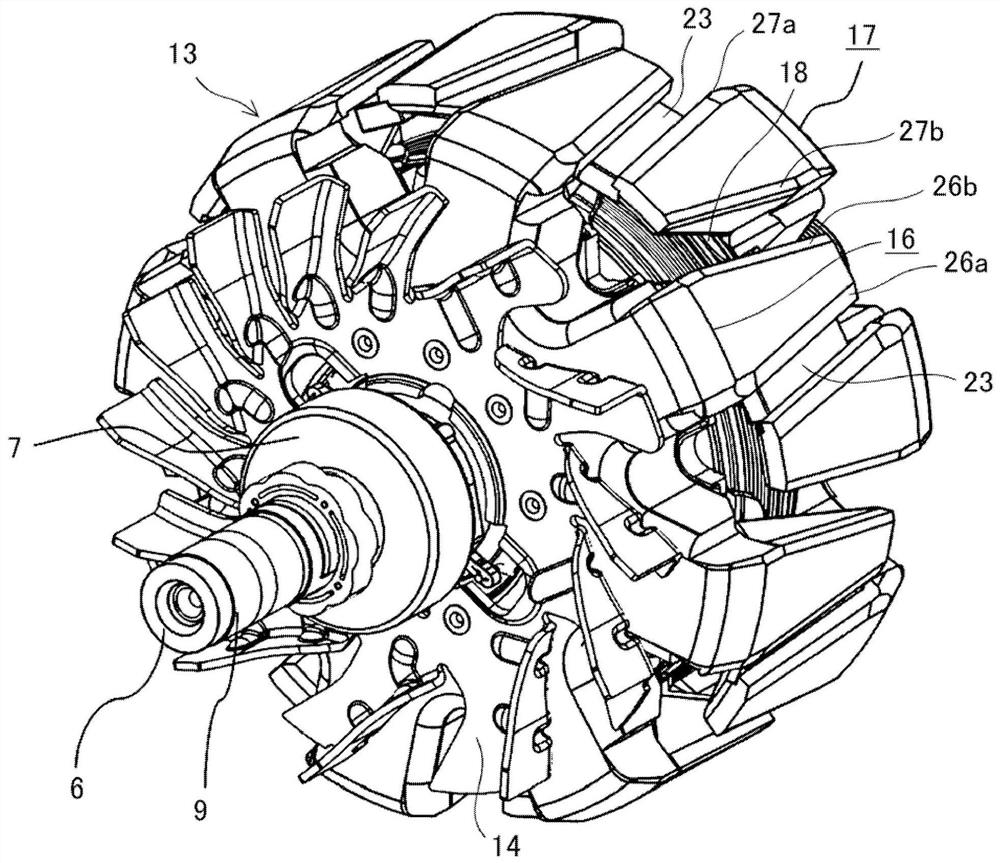
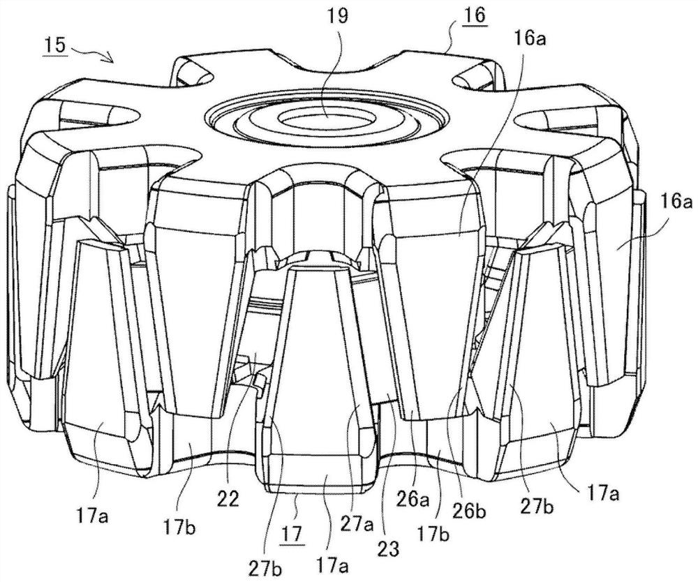
[0049] figure 1 is a cross-sectional view schematically showing the rotating electric machine according to Embodiment 1, figure 2 is a schematic external view showing the rotor of the rotating electric machine according to Embodiment 1, image 3 is a perspective view showing a schematic appearance of a pole core body to which the rotor of the rotating electric machine according to Embodiment 1 is applied, Figure 4 It is a perspective view which shows the 1st pole which comprises the schematic appearance of a pole core body. exist Figure 1 to Figure 4 Among them, a rotating electric machine 1 as an AC generator motor for vehicles is divided into a rotating machine part 2 and an electric equipment part 3. The electric equipment part 3 is configured to supply electric power to a rotor winding 18 via a brush 8 and a slip ring 9, and is equipped with There are a power circuit unit and the like for supplying electric power to the stator winding 12 .
[0050] The shaft 6 of th...
Embodiment approach 2
[0064] Figure 17 It is a cross-sectional view showing the vicinity of the first pole 16 and the second pole 17 of the rotor and the first claw-shaped magnetic pole portion 16 a and the second claw-shaped magnetic pole portion 17 a of the permanent magnet 23 in the second embodiment. The width WMa in the rotational direction of the first chamfered portion 26a and the second chamfered portion 27a adjacent to the inter-magnetic pole portion 22a where the permanent magnet 23 is inserted is made larger than the first chamfered portion adjacent to the magnetic pole interpole portion 22b where the permanent magnet 23 is not inserted. 26b and the second chamfered portion 27b have a large rotational width WMb.
[0065] According to the second embodiment, since the first chamfered portion 26a and the second chamfered portion 27a adjacent to the inter-magnetic pole portion 22a where the permanent magnet 23 is inserted are configured so as to be adjacent to the first inter-magnetic pole ...
Embodiment approach 3
[0067] Figure 18 It is a cross-sectional view showing the vicinity of the first pole 16 and the second pole 17 of the rotor and the first claw-shaped magnetic pole portion 16a and the second claw-shaped magnetic pole portion 17a of the permanent magnet 23 according to the third embodiment. The rotational width WMa of the first chamfered portion 26 a and the second chamfered portion 27 a adjacent to the magnetic pole interpole portion 22 a inserted in the permanent magnet 23 is made wider than half Wrh of the radial width of the magnetic flux output surface of the permanent magnet 23 .
[0068] The magnetic flux generated by the permanent magnet 23 is divided into a magnetic circuit and an output magnetic flux 29, wherein the magnetic circuit forms a leakage magnetic flux passing through the second magnetic flux regulating part 25a via the first magnetic flux regulating part 24a and closing in the rotor 28 , the output magnetic flux 29 passes from the first claw-shaped magneti...
PUM
 Abstract
Description
Claims
Application Information
 - R&D Engineer
- R&D Manager
- IP Professional
- Industry Leading Data Capabilities
- Powerful AI technology
- Patent DNA Extraction
Browse by: Latest US Patents, China's latest patents, Technical Efficacy Thesaurus, Application Domain, Technology Topic, Popular Technical Reports.
© 2024 PatSnap. All rights reserved.Legal|Privacy policy|Modern Slavery Act Transparency Statement|Sitemap|About US| Contact US: help@patsnap.com


