
Electric vehicle charging and discharging facility planning configuration method for load balancing

An electric vehicle, load balancing technology, applied in electric vehicles, battery circuit devices, AC network load balancing, etc., can solve the problem of lack of regional distribution peak and valley difference, aggravating load imbalance, V2G load balancing, and difficulty in increasing the capacity of distribution stations. , Affect the reliability and economy of distribution transformers, and achieve the effect of enhancing the load capacity and balance control ability, avoiding the hidden danger of overloading distribution transformers, and alleviating the problems of distribution transformer transformation.

Active Publication Date: 2021-06-18
ZHEJIANG DAYOU IND CO LTD HANGZHOU SCI TECH DEV BRANCH CO
View PDF7 Cites 3 Cited by
  • Summary
  • Abstract
  • Description
  • Claims
  • Application Information

AI Technical Summary

Problems solved by technology

On the one hand, the growing demand for electric vehicle charging is unbalanced with the development of charging facilities. It is difficult to increase the capacity of existing distribution stations. The peaks of the basic load overlap, and the problem of peak-on-peak is becoming more and more serious, seriously affecting the reliability and economy of the distribution transformer; a new approach
[0003] At present, the research on electric vehicle charging facilities mainly focuses on the site selection and fixed capacity of charging stations, and most of them are planned on the premise that the distribution network can be expanded and transformed, but there is a lack of research on the aggravation of regional power distribution peak-valley differences, load imbalance, V2G Research on issues such as load balancing is difficult to meet the growing demand for electric vehicle charging, and it is also unable to effectively utilize the load balancing capabilities of electric vehicle charging and discharging facilities

Method used

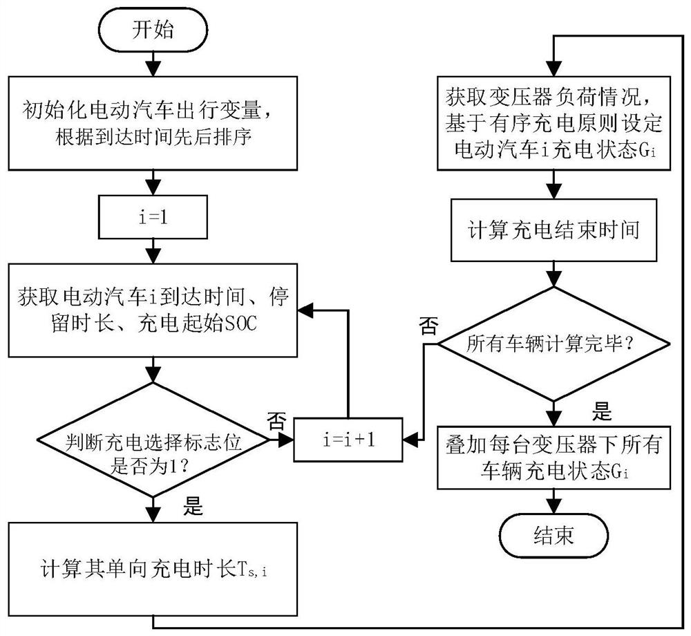
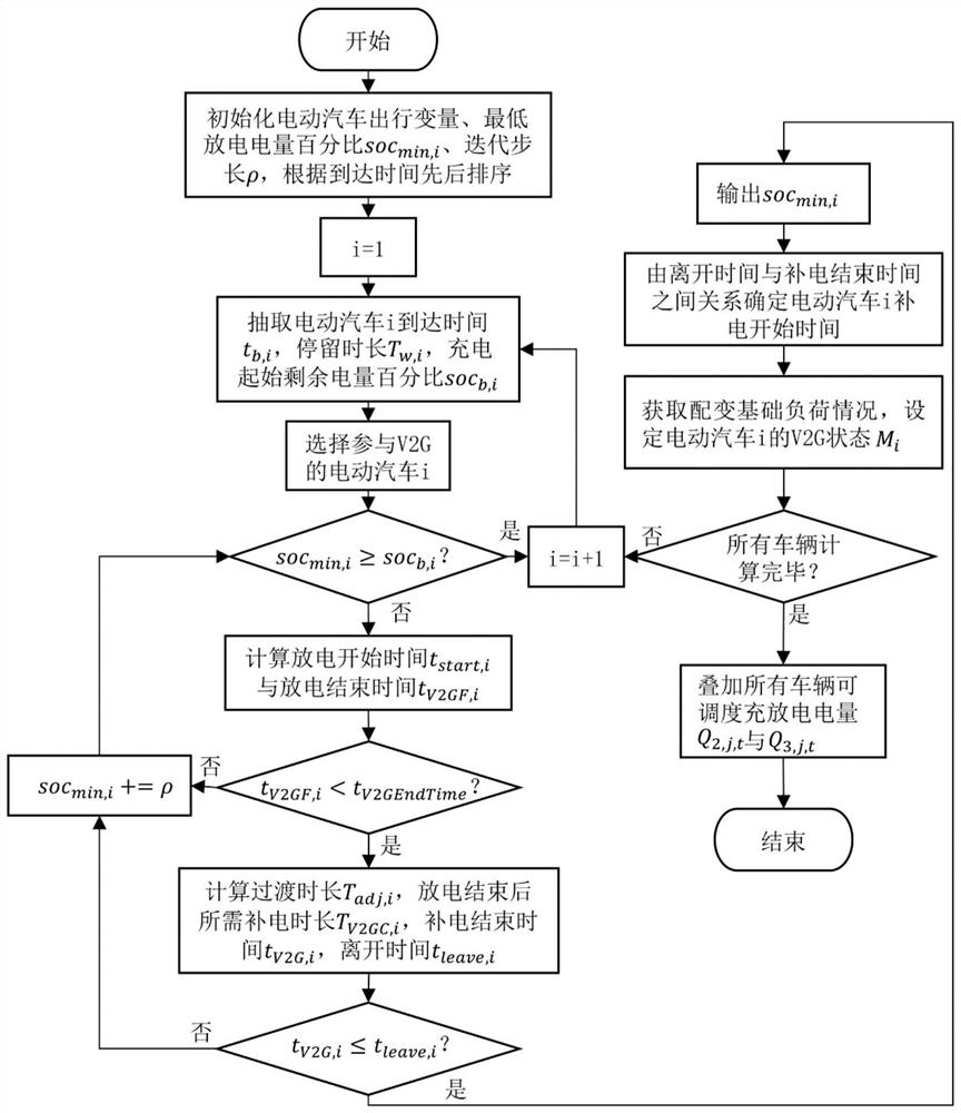

Image

  • Electric vehicle charging and discharging facility planning configuration method for load balancing
  • Electric vehicle charging and discharging facility planning configuration method for load balancing
  • Electric vehicle charging and discharging facility planning configuration method for load balancing

Examples


Embodiment Construction

[0081] The technical solutions in the embodiments of the present invention will be clearly and completely described below with reference to the accompanying drawings in the embodiments of the present invention. Obviously, the described embodiments are only a part of the embodiments of the present invention, but not all of the embodiments. The following description of at least one exemplary embodiment is merely illustrative in nature and is in no way intended to limit the invention, its application, or uses. Based on the embodiments of the present invention, all other embodiments obtained by those of ordinary skill in the art without creative efforts shall fall within the protection scope of the present invention.

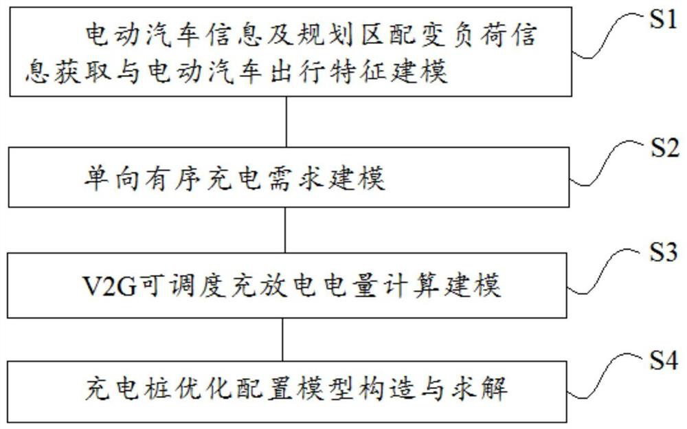
[0082] refer to figure 1 As shown, a method for planning and configuring electric vehicle charging and discharging facilities for load balancing includes the following steps:

[0083] S1: Acquisition of electric vehicle information and distribution transformer load...


PUM


Abstract

The invention belongs to the technical field of charging, and particularly relates to an electric vehicle charging and discharging facility planning and configuration method for load balancing. The method comprises the following steps: S1, obtaining electric vehicle information and planning area distribution transformer load information, and modeling electric vehicle travel characteristics; S2, modeling a one-way ordered charging demand; S3, carrying out V2G schedulable charging and discharging electric quantity calculation modeling; and S4, constructing and solving an optimal configuration model of the charging pile. The load accommodating capacity and the balance regulation and control capacity of a distribution transformer in the planning area are enhanced, the reliability and economy of the distribution network in the planning area and the charging requirement of the electric vehicle are considered, and the distribution transformer transformation problem is relieved.

Description

technical field [0001] The invention belongs to the technical field of charging, and in particular relates to a method for planning and configuring electric vehicle charging and discharging facilities for load balancing. Background technique [0002] In recent years, my country's power load has been increasing. At the same time, with the development of the electric vehicle industry, the impact of electric vehicles on regional distribution transformers is increasing. On the one hand, the growing demand for electric vehicle charging is unbalanced with the development of charging facilities. It is difficult to increase the capacity of existing distribution stations. The peaks of the basic load overlap, and the problem of peak-on-peak is becoming more and more serious, seriously affecting the reliability and economy of the distribution transformer; A new approach. [0003] At present, the research on electric vehicle charging facilities mainly focuses on the site selection an...

Claims


Application Information

Patent Timeline
IPC IPC(8): H02J3/32H02J3/26B60L55/00H02J7/00
CPCH02J3/322H02J3/26B60L55/00H02J7/0048H02J2203/20Y02E40/50
Inventor 吴靖司为国郑伟彦朱超越蒋燕萍金明
Owner ZHEJIANG DAYOU IND CO LTD HANGZHOU SCI TECH DEV BRANCH CO
Learn More