
Thermal imaging image attenuation device, control module and thermal imaging equipment

An attenuation device and thermal imaging technology, applied in the field of infrared imaging, can solve the problems of high cost, large volume, and low precision of the thermal image of the measured high temperature target, and achieve the effect of convenient position adjustment

Active Publication Date: 2021-06-18
HANGZHOU HIKMICRO SENSING TECH CO LTD
View PDF7 Cites 0 Cited by
  • Summary
  • Abstract
  • Description
  • Claims
  • Application Information

AI Technical Summary

Problems solved by technology

However, the existing attenuation device is bulky and expensive, and the working position of the attenuation sheet of

Method used


Image

  • Thermal imaging image attenuation device, control module and thermal imaging equipment
  • Thermal imaging image attenuation device, control module and thermal imaging equipment
  • Thermal imaging image attenuation device, control module and thermal imaging equipment

Examples


Embodiment Construction

[0028] Reference will now be made in detail to the exemplary embodiments, examples of which are illustrated in the accompanying drawings. When the following description refers to the accompanying drawings, the same numerals in different drawings refer to the same or similar elements unless otherwise indicated. The implementations described in the following exemplary embodiments do not represent all implementations consistent with this application. Rather, they are merely examples of apparatuses and methods consistent with aspects of the present application as recited in the appended claims.

[0029] The terminology used in this application is for the purpose of describing particular embodiments only, and is not intended to limit the application. As used in this application and the appended claims, the singular forms "a", "the", and "the" are intended to include the plural forms as well, unless the context clearly dictates otherwise. It should also be understood that the term...


PUM


Abstract

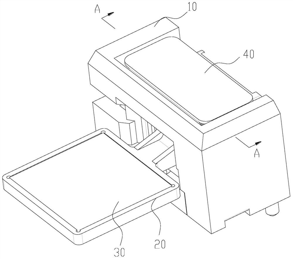
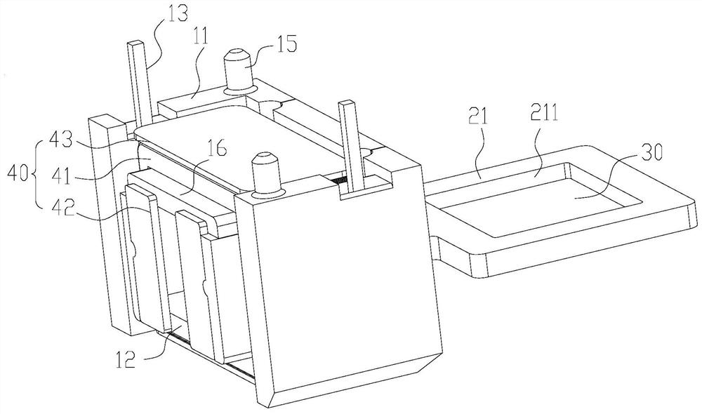
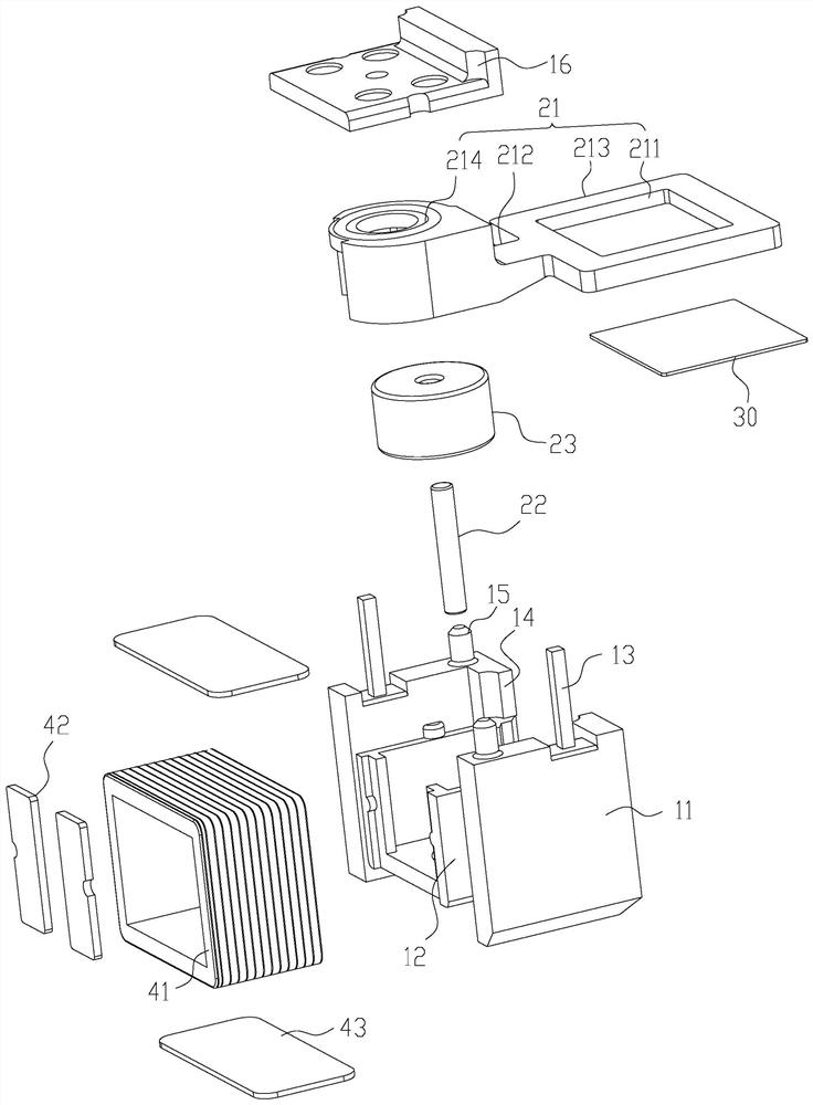
The invention provides a thermal imaging image attenuation device, a control module and thermal imaging equipment. The thermal imaging image attenuation device comprises a base, a driving part installed on the base, a cantilever assembly movably connected to the base and an attenuation piece installed on the cantilever assembly, the attenuation piece is located outside the base, and the driving part is in driving connection with the cantilever assembly. The cantilever assembly is driven by the driving part to move relative to the base so as to adjust the working position of the attenuation piece. The attenuation piece is installed on the cantilever assembly and moves along with the cantilever assembly, the working position of the attenuation piece can be changed by adjusting the relative position between the cantilever assembly and the base, and position adjustment is convenient.

Description

technical field [0001] The application belongs to the technical field of infrared imaging, and relates to a thermal imaging image attenuation device, a control module and thermal imaging equipment. Background technique [0002] The thermal imager uses an infrared detector and an optical imaging objective lens to receive the infrared radiation energy of the measured target, and reflects the energy distribution pattern to the photosensitive element of the infrared detector, thereby obtaining an infrared thermal image. corresponding to the heat distribution field. [0003] When the measured target collected by the thermal imager is a high-temperature target with a temperature exceeding 550 degrees, the thermal imager cannot directly receive the infrared radiation energy of the measured target. In related technologies, a thermal imager needs to be equipped with a corresponding attenuation device to increase the temperature measurement range of the thermal imager. However, the ...

Claims


Application Information

Patent Timeline
IPC IPC(8): G01J5/08G01J5/02G01J5/04
CPCG01J5/0205G01J5/047G01J2005/0077G01J5/0816
Inventor 徐伟
Owner HANGZHOU HIKMICRO SENSING TECH CO LTD
Learn More