
Drum brake

A technology of drum brakes and brake drums, which is applied in the direction of mechanically driven drum brakes, brake types, brake components, etc., which can solve the problems of easy falling off of screws, large heat generation, poor heat dissipation, etc., and achieve heat dissipation Fast, prevent overheating effect

Active Publication Date: 2021-06-18
龙口市胶东机械配件有限公司
View PDF9 Cites 0 Cited by
  • Summary
  • Abstract
  • Description
  • Claims
  • Application Information

AI Technical Summary

Problems solved by technology

However, there are some problems in drum brakes at present: 1. After the brake shoe inside the drum brake is worn out, it needs to be adjusted by screws. When the wheel vibrates, the screws are driven to rotate, and the screws are easy to fall off during the rotation; 2. 1. When the drum brake is in use, due to the large contact area, a large amount of heat will be generated during the braking process, and the heat dissipation effect is not good. When the heat is too large, it is easy to cause brake failure and cause danger.

Method used


Image

  • Drum brake
  • Drum brake
  • Drum brake

Examples


Embodiment

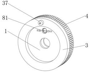
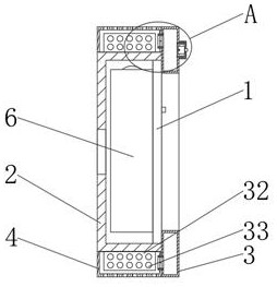
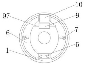
[0025] A drum brake, comprising a bottom plate 1, a brake drum 2, a water tank 3, a protective cover 4, a hinged frame 5, a brake shoe 6, a limit screw 7, an inner ring gear 8, an adjustment cylinder 9 and a short shaft 95, the The outer side of the bottom plate 1 is rotatably connected with a brake drum 2, the outer side of the bottom plate 1 is fixedly connected with a water tank 3, the water tank 3 is in contact with the brake drum 2, and the water tank 3 is fixedly connected with a protective cover 4. The protective cover 4 is rotatably connected with the brake drum 2, the outer side of the bottom plate 1 is fixedly connected with a hinged frame 5, and the inner side of the hinged frame 5 is hinged with two symmetrically distributed brake shoes 6, the brake shoes 6 and A torsion spring is connected between the hinged frames 5, and a driver 10 is fixedly connected to the outside of the bottom plate 1, and the driver 10 is in contact with the brake shoe 6, and the brake shoe ...


PUM


Abstract

The invention discloses a drum brake which comprises a bottom plate, a brake drum, a water tank, a protective cover, a hinge frame, brake shoes, a limiting screw, an inner gear ring, an adjusting cylinder and a short shaft, wherein the brake drum is rotationally connected to the outer side of the bottom plate, the water tank is fixedly connected to the outer side of the bottom plate and makes contact with the brake drum, the protective cover is fixedly connected to the water tank, the protective cover is rotationally connected with the brake drum, the hinge frame is fixedly connected to the outer side of the bottom plate, two symmetrically-distributed brake shoes are hinged to the inner side of the hinge frame, a driver is fixedly connected to the outer side of the bottom plate, the driver makes contact with the brake shoes, the brake shoes make contact with the bottom plate, an adjusting cylinder is fixedly connected to the bottom plate, and an inner gear ring is fixedly connected to the interior of the bottom plate. The drum brake has the characteristics of being good in heat dissipation effect and capable of preventing a rotary disc from rotating.

Description

technical field [0001] The invention belongs to the technical field of brakes, in particular to a drum brake. Background technique [0002] Drum brakes are also called block brakes, and brakes are achieved by pressing the brake pads on the brake wheels. Drum brakes are an early design of the braking system. The design of the brake drum has been used on horse-drawn carriages in 1902, and it was not widely used in the automobile industry until around 1920. The mainstream of drum brakes is the internal tension type. Its brake block (brake shoe) is located on the inner side of the brake wheel. When braking, the brake block opens outwards and rubs against the inner side of the brake wheel to achieve the purpose of braking. However, there are some problems in drum brakes at present: 1. After the brake shoe inside the drum brake is worn out, it needs to be adjusted by screws. When the wheel vibrates, the screws are driven to rotate, and the screws are easy to fall off during the r...

Claims


Application Information

Patent Timeline
IPC IPC(8): F16D51/22F16D65/10F16D65/827F16D65/833F16D66/02
CPCF16D51/22F16D65/10F16D65/827F16D65/833F16D66/02
Inventor 李兵
Owner 龙口市胶东机械配件有限公司
Learn More