
A house security appraisal device and using method thereof

A technology for safety appraisal and housing, applied in the direction of measuring devices, instruments, machines/supports, etc., can solve the problems of high manufacturing cost, easy damage, and large errors of electronic equipment, and achieve the effect of reducing errors and accurate detection results

Active Publication Date: 2022-05-27
广东稳固检测鉴定有限公司
View PDF18 Cites 0 Cited by
  • Summary
  • Abstract
  • Description
  • Claims
  • Application Information

AI Technical Summary

Problems solved by technology

[0003] At present, most of the existing house safety appraisal devices use electronic level and vertical instruments for the detection of inclination. The electronic equipment has large errors in detection, is easy to damage, and has high manufacturing costs.

Method used


Image

  • A house security appraisal device and using method thereof
  • A house security appraisal device and using method thereof
  • A house security appraisal device and using method thereof

Examples


Embodiment 1

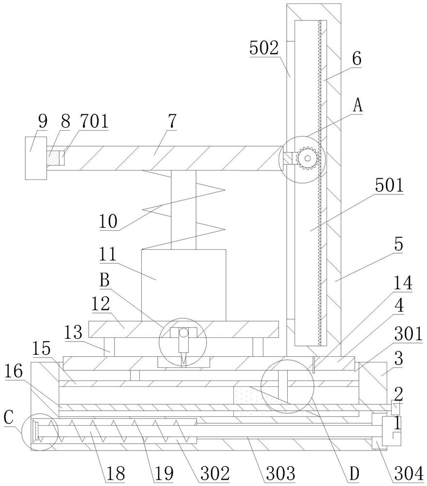
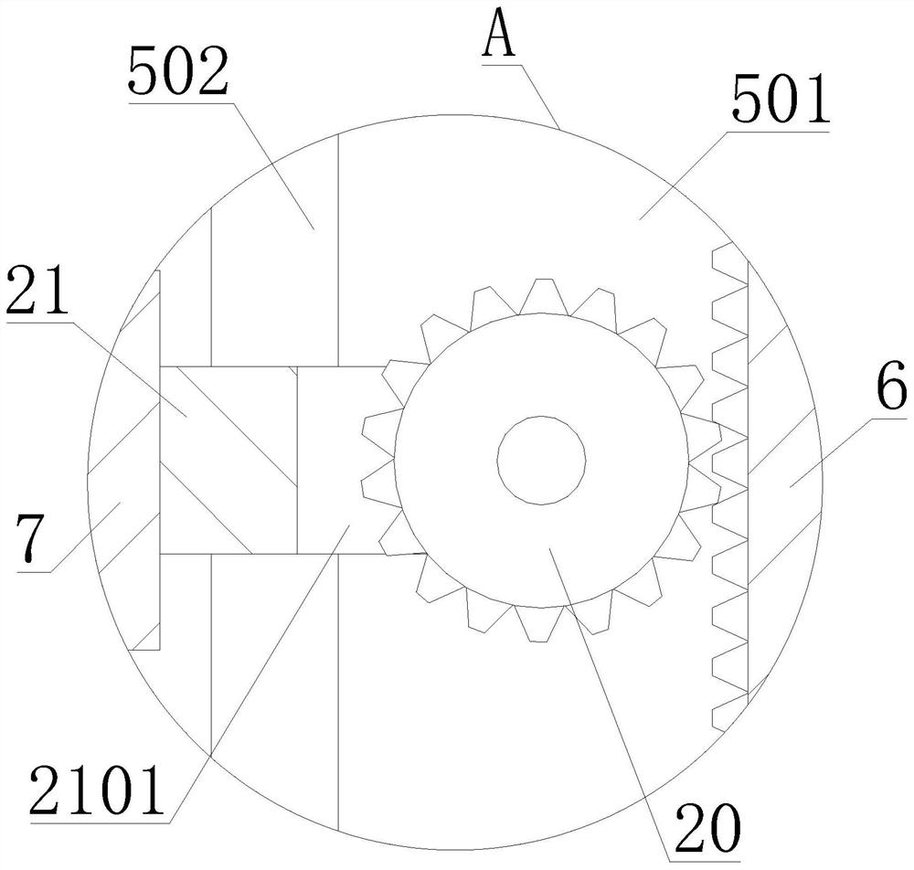
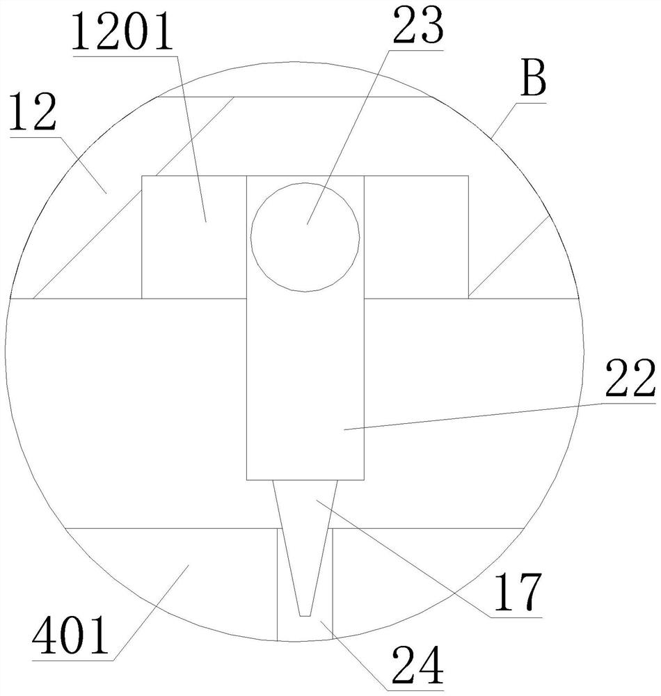
[0039] like Figure 1-5 As shown in the figure, a house safety appraisal device proposed by the present invention includes a base 3, a mounting plate 4, a fixing plate 5, a measuring rod 7, a lifting device 11, a supporting plate 12, a supporting column 13, a second pointer 14, and a partition plate 15. , threaded rod 16, first pointer 17, rotating rod 22, fixed shaft 23, sliding rod 26, slider 27 and connecting column;

[0040] The fixing plate 5 is installed on the base 3, and the fixing plate 5 is provided with a first scale line; the base 3 is provided with a first installation groove 301; the first installation groove 301 is provided with a second scale line;

[0041] The partition plate 15 is installed in the first installation groove 301; the threaded rod 16 is rotatably arranged in the first installation groove 301, one end of the threaded rod 16 passes through the base 3, and the threaded rod 16 is located under the partition plate 15; the slider 27 is threadedly conn...

Embodiment 2

[0057] A method of using a house safety identification device provided by the present invention includes the house safety identification device in Embodiment 1, and specifically includes:

[0058] S1. Place the base 3 indoors, and connect the base 3 to the wall through the limit component;

[0059] S2, observe the relative position of the first pointer 17 and the calibration line 24;

[0060] S3. Rotate the threaded rod 16 to drive the slider 27 to move, so that the second inclined surface 271 is slidably connected to the first inclined surface 261, and the sliding rod 26 is slidably connected to the partition plate 15 to move the mounting plate 4, so that the mounting plate 4 is inclined and rotated. The rod 22 drives the first pointer 17 to rotate until the first pointer 17 is located in the calibration line 24;

[0061] S4, start the lifting device 11, and drive the measuring rod 7 to slide and connect to the fixed plate 5, so that the end of the measuring rod 7 away from ...


PUM


Abstract

A house safety identification device, comprising a base, a mounting plate, a fixed plate, a measuring rod, a lifting device, a supporting plate, a supporting column, a second pointer, a partition plate, a threaded rod, a rotating rod, a fixed shaft, a sliding rod and a slider; A first scale line is arranged on the fixing plate; a second scale line is arranged on the base; the partition plate is installed on the base; the threaded rod is rotated and arranged on the base; The installation plate is connected by rotation; the sliding rod is connected to the installation plate; the installation plate is provided with a calibration line; the second pointer is installed on the installation plate; the support plate is connected to the installation plate; the fixed shaft is connected to the support plate; There is a first pointer; the lifting device is connected to the measuring rod; the measuring rod is slidably connected to the fixing plate; a limit component is arranged on the base. The invention also provides a method for using the house safety identification device. The invention reduces the error of the electronic equipment by manually leveling the measurement, so that the detection result is more accurate.

Description

technical field [0001] The invention relates to the technical field of house detection, in particular to a house safety identification device and a method for using the same. Background technique [0002] In the house safety appraisal, the tilt angle of the house is one of the most important items. The tilt angle of the building mainly means that the deviation of the building from the vertical position is greater than 0, which is called the tilt of the building; the reason for the tilt of the building is mainly due to the insufficient bearing capacity of the foundation. As a result, the settlement of the foundation causes the house to tilt to one side; the uneven subsidence of the house foundation is the main reason for the tilt of the house. The subsidence of the house is mainly divided into two categories: one is uniform settlement, and the other is uneven settlement. [0003] At present, most of the existing house safety identification devices for tilt detection use an el...

Claims


Application Information

Patent Timeline
Patent Type & Authority Patents(China)
IPC IPC(8): G08B21/24F16M11/04F16M13/02G01C9/00G01C9/02
CPCG08B21/24G01C9/00G01C9/02F16M13/02F16M11/04
Inventor 刘立创邓锦尚刘俊伟龙耀坚熊能邝炳添孙冬菊骆志昭朱建科黄刚张文东郭润华梁俊健
Owner 广东稳固检测鉴定有限公司
Learn More