Lifting device for building decoration and lifting method thereof

A construction and telescopic pole technology, applied in the direction of construction, building structure, housing structure support, etc., can solve the problems of poor personal safety, reduce work efficiency, affect work progress, etc., save labor output, improve work efficiency, improve safety effect

Pending Publication Date: 2021-06-15
陈晓蓉
View PDF6 Cites 1 Cited by
  • Summary
  • Abstract
  • Description
  • Claims
  • Application Information

AI Technical Summary

Problems solved by technology

[0003] In the existing patented technology CN108331318B, the lowering of the lifting platform is used to drive the guide bar to move downward, so that the rollers at the lower end of the lever plate lift up the entire device, thereby realizing the switching between device fixing and transportation, but there are following defects in the realization process: When the roller moves the position of the device, the working platform needs to be lowered. When construction needs to be carried out at the same horizontal position, repeated lifting and lowering of the working platform will affect the progress of the work, and it will take a lot of time to adjust the height of the working platform to the original construction position, which will further reduce the work Efficiency. In addition, when personnel work at high places, due to poor protection measures, the personal safety of personnel is poor, and they need to move to work at high places. During the movement, personnel need to get off the construction platform and then move the lifting device. A waste of time, resulting in poor work efficiency

Method used


Image

  • Lifting device for building decoration and lifting method thereof
  • Lifting device for building decoration and lifting method thereof
  • Lifting device for building decoration and lifting method thereof

Examples


Embodiment

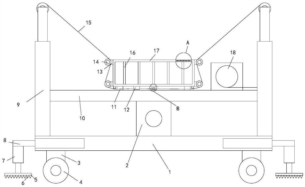
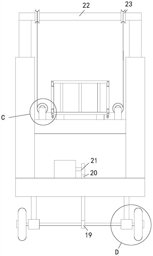
[0034] see Figure 1-7, a lifting device for building decoration, comprising a chassis 1 and a load basket 17, the left end and the right end of the chassis 1 are provided with a telescopic rod 2 8, and the bottom end of the output end of the telescopic rod 2 8 is provided with a telescopic rod 1 7, The output ends of each telescopic rod-7 are provided with support plates 5, and the four corners of the bottom of the chassis 1 are provided with supporting legs 3, and the bottom ends of each supporting legs 3 are provided with axle sleeves 33, and each axle sleeve 33 The circumferential inner walls of the shafts 32 are rotatably connected with the shaft 32, and the front end and the rear end of the shaft 32 pass through the shaft sleeve 33, and extend to the outside of the shaft sleeve 33. The roller 4 is sleeved, and the middle part of the connecting shaft 32 at the left end is set with a transmission wheel one 19, the top middle part of the chassis 1 is provided with a motor o...


PUM


Abstract

The invention relates to the technical field of decoration, in particular to a lifting device for building decoration and a lifting method thereof. The lifting device comprises a base plate and a bearing basket, wherein telescopic rods II are respectively arranged on the left end and the right end of the base plate, telescopic rods I are respectively arranged on the bottom ends of the output ends of the telescopic rods II, support plates are respectively arranged on the output ends of the telescopic rods I, a transmission wheel II is arranged on the output end of a motor I, connecting rods are respectively connected to the top end of a telescopic rod III which is located on the front end and the top end of a telescopic rod III which is located on the rear end, pulleys II are symmetrically arranged on the circumferential outer wall of the connecting rods from front to back, connecting plates are connected to the middle of the telescopic rod III, winches are arranged on the right sides of the top ends of the connecting plates, wire ropes are arranged in the winches, connecting rods III are respectively arranged at the four corners of the bottom end of the bearing basket, and pulleys IV are respectively arranged on the bottom ends of the connecting rods III, so that high personal safety protection is achieved, and people do not need to go down to move in the moving process.

Description

technical field [0001] The invention relates to the technical field of decoration, in particular to a raising device for building decoration and a raising method thereof. Background technique [0002] As we all know, architectural decoration is generally divided into indoor decoration and outdoor decoration. Outdoor decoration generally includes wall decoration, pavement decoration and nursery decoration, etc. Interior decoration includes room design, decoration, furniture arrangement and various small decorations. Construction, not only during the decoration design and construction period, but also includes long-term continuous decoration after living in. It is inevitable to work at high places in building decoration, and at this time, a device that can adjust the working height is needed. [0003] In the existing patented technology CN108331318B, the lowering of the lifting platform is used to drive the guide bar to move downward, so that the rollers at the lower end of t...

Claims


Application Information

Patent Timeline
IPC IPC(8): E04G1/24E04G1/18
CPCE04G1/24E04G1/18E04G2001/242
Inventor 陈晓蓉
Owner 陈晓蓉
Why Eureka
Try Eureka