Vehicle stopping device
A technology of blocking cars and blocking nets, which is applied in roads, restricted traffic, roads, etc., can solve the problems of long deployment time of flexible car blocking devices, long braking distance, poor blocking effect, etc., and achieves shortened braking distance and small damage , long service life effect
- Summary
- Abstract
- Description
- Claims
- Application Information
AI Technical Summary
Problems solved by technology
Method used
Image
Examples
Embodiment 1
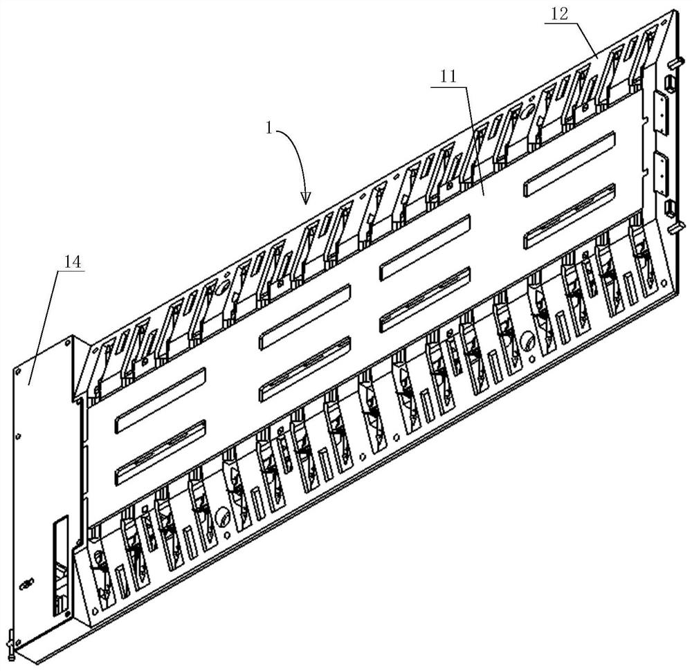
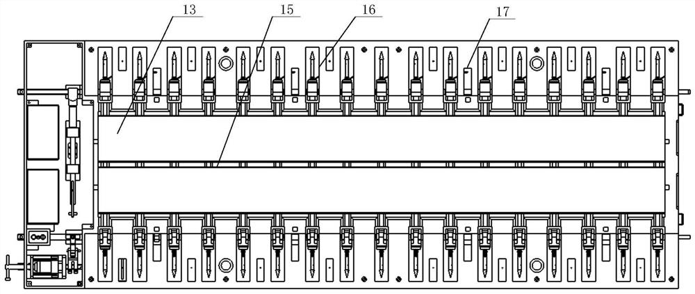
[0069] like Figure 1-Figure 13 As shown, a vehicle blocking device includes a support frame 1, a rotating mechanism 2 and a blocking net 3;
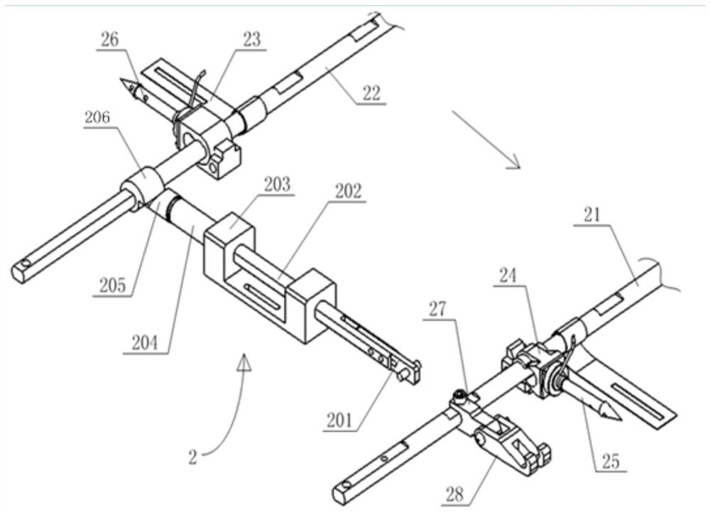
[0070] The rotating mechanism 2 is installed on the support frame 1, and the rotating mechanism 2 includes a first rotating shaft 21, a second rotating shaft 22 and a link mechanism;
[0071] The first rotating shaft 21 and the second rotating shaft 22 are installed on both sides of the support frame 1 respectively, the first rotating shaft 21 and the second rotating shaft 22 are provided with shrapnel 23, and the first rotating shaft 21 is connected with the fixing seat 24 The first air discharge nail 25 is connected, the second rotating shaft 22 is connected with the second air discharge nail 26 through the fixing seat 24, and the first air discharge nail 25 and the second air discharge nail 26 can be separated from the fixing seat under the action of external force twenty four;
[0072] When the first rotating shaft 21 rotates to t...
Embodiment 2
[0089] This embodiment is based on embodiment 1, and the difference with embodiment 1 is:
[0090] The driving mechanism includes a first motor and a second motor, and the first motor and the second motor are respectively used to drive the first rotating shaft 21 and the second rotating shaft 22 to rotate.
[0091] In this embodiment, the first rotating shaft 21 and the second rotating shaft 22 are directly driven and rotated by the first motor and the second motor, and there is no need for a link mechanism and an elastic piece 23 .
[0092] The working process of this embodiment is as follows:
[0093] When it is necessary to block the car, the first rotating shaft 21 is driven by the first motor to rotate, so that the first discharge air nail 25 is rotated to the working state and inserted into the front wheel of the car, and one end of the blocking net 3 is wound on the front wheel, and then The second rotating shaft 22 is driven by the second motor to rotate, so that the ...
Embodiment 3
[0095] like Figure 1-Figure 13 As shown, this embodiment is based on Embodiment 1, and one end of the sliding shaft 202 is provided with a square groove, and the magnetic hanging rod 201 is installed in the square groove through bolts or screws; the hook 28 is rotatably arranged on the fixed block 27; The cavity is provided with a partition 15, the blocking net 3 is folded and placed in the cavity, the bottom plate 13 is provided with a linkage chamber 14 for installing a linkage mechanism; the guide base 203 is a U-shaped structure, the The sliding shaft 202 passes through the two side walls of the U-shaped structure.
PUM
 Abstract
Description
Claims
Application Information
 - Generate Ideas
- Intellectual Property
- Life Sciences
- Materials
- Tech Scout
- Unparalleled Data Quality
- Higher Quality Content
- 60% Fewer Hallucinations
Browse by: Latest US Patents, China's latest patents, Technical Efficacy Thesaurus, Application Domain, Technology Topic, Popular Technical Reports.
© 2025 PatSnap. All rights reserved.Legal|Privacy policy|Modern Slavery Act Transparency Statement|Sitemap|About US| Contact US: help@patsnap.com


