Crane lifting device

A lifting device and crane technology, applied in the direction of lifting device, mechanical equipment, spring/shock absorber, etc., can solve the problems of falling objects, hurt people, inconvenient use, etc., and achieve the convenience of wheel movement and safety. good, balanced effect

Active Publication Date: 2021-06-15
重庆市巨亮机械制造有限责任公司
View PDF7 Cites 0 Cited by
  • Summary
  • Abstract
  • Description
  • Claims
  • Application Information

AI Technical Summary

Problems solved by technology

[0003] However, the existing crane lifting device lacks fall buffer protection. Once a sharp fall occurs, the lifted object will fall, which may cause injury; the existing lifting device lacks a good counterweight structure, which leads to the balance of the crane. Poor performance; when the existing crane lifting device is moving, it is inconvenient to locate the moving mechanism, such as the wheel structure, which needs to be positioned one by one, which is inconvenient to use

Method used


Image

  • Crane lifting device
  • Crane lifting device
  • Crane lifting device

Examples


Embodiment

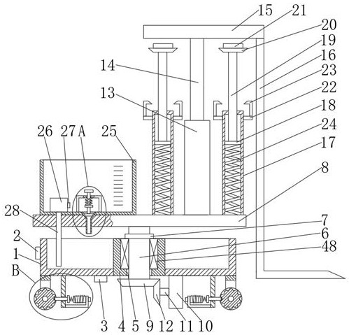
[0029] A lifting device for a crane, comprising a box body 1 filled with water, the outside of the box body 1 is provided with a switch 2, the lower end of the box body 1 is provided with a battery 3, the box body 1 The middle part is fixedly connected with a support sleeve 4, and the lower end of the support sleeve 4 is provided with a shaft hole 5, and a main shaft 6 is rotatably connected in the shaft hole 5, and a bearing 48 is fixedly installed in the support sleeve 4, and the inside of the bearing 48 The main shaft 6 is fixedly sleeved, the outside of the main shaft 6 is provided with a limit ring 7, the lower end of the limit ring 7 is in contact with the inner ring of the bearing 48, and the upper end of the main shaft 6 is fixedly connected with a turntable 8, the The lower end of the main shaft 6 is fixedly connected with a driven bevel gear 9, and the lower end of the casing 1 is fixedly equipped with a motor 10. The motor 10 is a forward and reverse motor, which bel...


PUM


Abstract

The invention discloses a crane lifting device. The crane lifting device comprises a box body, wherein a switch is arranged at the outer side of the box body, a storage battery is arranged at the lower end of the box body, a supporting sleeve is fixedly connected to the middle of the box body, a shaft hole is formed in the lower end of the supporting sleeve, a main shaft is rotationally connected into the shaft hole, and a bearing is fixedly installed in the supporting sleeve; the main shaft is fixedly sleeved with the bearing, a limiting ring is arranged on the outer side of the spindle, the lower end of the limiting ring makes contact with an inner ring of the bearing, a rotating table is fixedly connected to the upper end of the main shaft, a driven bevel gear is fixedly connected to the lower end of the main shaft, and a motor is fixedly installed at the lower end of the box body; and the tail end of a motor shaft of the motor is fixedly connected with a driving bevel gear, and the driving bevel gear is meshed with the driven bevel gear. The invention relates to the crane lifting device. The crane lifting device has the characteristics that the counterweight is adjustable, falling is buffered and protected, and positioning is convenient.

Description

technical field [0001] The invention belongs to the technical field of cranes, in particular to a crane lifting device. Background technique [0002] Lifting is the process of transporting machinery or other objects from one place to another. Most hoisting machines start vertical or vertical and horizontal working strokes after the spreader picks up the material, unload after reaching the destination, and then empty travel to the picking place to complete a working cycle, and then perform the second work. All kinds of hoisting machinery have different purposes and have great differences in structure, but they all have a lifting mechanism to realize the basic action of lifting. [0003] However, the existing crane lifting device lacks fall buffer protection. Once a sharp fall occurs, the lifted object will fall, which may cause injury; the existing lifting device lacks a good counterweight structure, which leads to the balance of the crane. Poor performance; the existing cr...

Claims


Application Information

Patent Timeline
Patent Type & Authority Applications(China)
IPC IPC(8): B66F9/06B66F9/075B66F9/20B66F9/22F16D63/00F16F15/067
CPCB66F9/06B66F9/075B66F9/07554B66F9/07572B66F9/20B66F9/22F16F15/067F16D63/006
Inventor 李培峨
Owner 重庆市巨亮机械制造有限责任公司
Why Eureka
Try Eureka