Pediatric clinical handheld laryngeal sputum suction assembly

A hand-held, throat technology, used in respirator, suction equipment, stereotaxic surgical instruments, etc., can solve the problems of inconvenient throat sputum suction, guide head throat blockage, suffocation, etc., and achieves simple operation and use. Convenient, easy-to-use effects

Inactive Publication Date: 2021-06-15
张爱莲
View PDF10 Cites 1 Cited by
  • Summary
  • Abstract
  • Description
  • Claims
  • Application Information

AI Technical Summary

Problems solved by technology

[0004] The purpose of the present invention is to solve the problem that the existing throat sputum suction assembly is inconvenient to suck the patient's throat sputum, and the

Method used


Image

  • Pediatric clinical handheld laryngeal sputum suction assembly
  • Pediatric clinical handheld laryngeal sputum suction assembly
  • Pediatric clinical handheld laryngeal sputum suction assembly

Examples


Embodiment 1

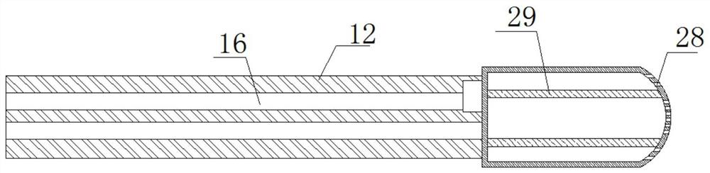
[0027] refer to Figure 1-5 , a pediatric clinical hand-held throat phlegm suction assembly, including a fixed ring 1, one side of the fixed ring 1 is rotatably connected with a swivel 2, two push rods 9 are fixedly installed on the swivel 2, and the fixed ring 1 slides on Four symmetrically arranged tie rods 3 are connected, one end of the tie rod 3 is fixedly installed with a clamping rod 4, the clamping rod 4 is fixedly installed with a stop rod 5, and the inner side of the fixing ring 1 is fixedly installed with four symmetrically arranged fixing rods 10, four The same positioning ring 11 is fixedly installed between the two fixing rods 10. A hose 12 is movably connected in the positioning ring 11. The hose 12 is provided with an air guide tube 16 and a liquid guide tube, and one end of the hose 12 is fixedly installed with a guide head 13. A box 14 is fixedly installed on the other end of the hose 12, a fixing seat 15 is fixedly installed on the bottom inner wall of the b...

Embodiment 2

[0036] refer to Figure 1-5 , a pediatric clinical hand-held throat sputum suction assembly, including a fixed ring 1, one side of the fixed ring 1 is rotatably connected with a swivel 2, the swivel 2 is welded with two push rods 9, and the fixed ring 1 is slidably connected There are four symmetrically arranged tie rods 3, one end of the tie rod 3 is welded with a clamping rod 4, the clamping rod 4 is welded with a stop rod 5, and the inner side of the fixing ring 1 is welded with four symmetrically arranged fixing rods 10, four fixing rods 10 The same positioning ring 11 is welded between them, and a hose 12 is movably connected in the positioning ring 11. The hose 12 is provided with an air guide tube 16 and a liquid guide tube. One end of the hose 12 is welded with a guide head 13. The other end is welded with a box body 14, a fixing seat 15 is welded on the bottom inner wall of the box body 14, two symmetrically arranged cavities 17 are opened on the fixing seat 15, and a...


PUM


Abstract

The invention belongs to the technical field of medical equipment, and particularly relates to a pediatric clinical handheld laryngeal sputum suction assembly. For the problems that an existing laryngeal sputum suction assembly cannot conveniently suck laryngeal sputum of a patient, a guide head, guided to the throat, of the existing laryngeal sputum suction assembly is prone to block the throat during sputum suction to cause suffocation, the following solution is proposed now that the pediatric clinical handheld laryngeal sputum suction assembly comprises a fixing ring; one side of the fixing ring is rotationally connected with a rotating ring; two push rods are fixedly installed on the rotating ring; four pull rods symmetrically arranged are slidably connected onto the fixing ring; a clamping rod is fixedly installed at one end of each pull rod; a blocking rod is fixedly installed on each clamping rod; four fixing rods symmetrically arranged are fixedly installed at the inner side of the fixing ring; a same positioning ring is fixedly installed among the four fixing rods; and a hose is movably connected into the positioning ring. The pediatric clinical handheld laryngeal sputum suction assembly is easy to operate and convenient to use, can conveniently support and open the oral cavity of a patient, or can guide out stasis and phlegm, or deliver oxygen, and is convenient for people to use.

Description

technical field [0001] The invention relates to the technical field of medical equipment, in particular to a pediatric clinical hand-held throat sputum suction assembly. Background technique [0002] Pediatrics is a comprehensive medical science that comprehensively studies physical and mental development, health care and disease prevention and treatment in children. All health and hygiene problems involving childhood and adolescence fall within the scope of paediatrics. The objects it treats are in the growth and development stage. In pediatric clinical operations, it is often necessary to aspirate sputum from the patient's throat. [0003] The existing laryngeal sputum suction assembly is inconvenient for sucking phlegm from the patient's throat, and the introduced guide head is easy to block the throat during suction, resulting in suffocation. Therefore, we designed a pediatric clinical hand-held device. Throat phlegm suction assembly. SUMMARY OF THE INVENTION [00...

Claims


Application Information

Patent Timeline
IPC IPC(8): A61M1/00A61M16/04A61B90/16
CPCA61B90/16A61M16/04A61M16/0463
Inventor 张爱莲张维良王成仁
Owner 张爱莲
Why Eureka
Try Eureka