
Die casting apparatus provided with movable electromagnetically controlled structure control module

A control module and electromagnetic control technology, applied in the field of die-casting devices, can solve the problems of increasing the strength of the tissue control module, affecting the shape stability and life, and reducing the temperature of molten metal, so as to improve the life and shape stability, increase the magnetic field strength, Effect of suppressing temperature rise

Active Publication Date: 2021-06-11
FUTURECAST
View PDF15 Cites 0 Cited by
  • Summary
  • Abstract
  • Description
  • Claims
  • Application Information

AI Technical Summary

Problems solved by technology

[0004] On the other hand, the structure control by electromagnetic field is to micronize the structure of solid particles by stirring the electromagnetic field during the process of forming a solid phase in the solid-liquid coexistence part injected into the alloy, such as Korean Patent Registration No. 10-0554093 and Korean Patent There is a limit to maximizing tissue control when the injected molten metal is completely in the liquid state or above the liquidus as suggested by Registration No. 10-0436118
The reason is that smooth texture control can be obtained in the high liquid coexistence part, but since the temperature of the molten metal is higher than the liquidus, there is a problem that the texture must be controlled after a predetermined delay time, and after the texture is controlled, the molten metal The temperature falls into the solid-liquid coexistence region, and the temperature becomes low enough to have sufficient fluidity, when the controlled molten metal is injected into the sleeve, the temperature of the molten metal decreases due to the low temperature of the sleeve, so that it cannot meet Working temperature of the molten metal injected into the cavity
[0005] In addition, as the technique introduced in Korean Patent Registration 10-0662034, in the case of inserting the tissue control module into the mold, in order to ensure the position of the tissue control module, most of the sleeve fixing position of the mold is removed, thus making the mold larger than the In addition, since the electromagnetic stirring device is surrounded by the tank and the mold, it receives the heat generated from the molten metal as it is, so the life of the electromagnetic stirring device is shortened, and the strength of the electromagnetic field is limited, so it may be difficult to apply the required electromagnetic field
[0006] In addition, since the area around the sleeve holding the sleeve is removed to insert the electromagnetic stirring device, the supporting force of the fixed mold or the bobbin around the sleeve is reduced, which may cause problems affecting shape stability and lifespan
[0007] In addition, in order to increase the strength of tissue control as in Korean Patent No. 10-1253605, the limited space in Korean Patent No. 10-0662034 becomes a problem, and in addition, the space for installing tissue control fixed on a fixed template becomes a problem. Problem, as in the case of Korean Patent Registration No. 10-0662034, due to the structure that the tissue control module is installed inside the device that accommodates a large amount of heat, there is a disadvantage that the problem of temperature rise of the coil module must be solved, increasing the strength of the tissue control module, Also limited by limited space and had very weak issues with securing the sleeve causing molten metal injection

Method used


Image

  • Die casting apparatus provided with movable electromagnetically controlled structure control module
  • Die casting apparatus provided with movable electromagnetically controlled structure control module
  • Die casting apparatus provided with movable electromagnetically controlled structure control module

Examples


Embodiment Construction

[0036] Hereinafter, exemplary embodiments of the present invention will be described in detail with reference to the accompanying drawings. The following embodiments are provided as examples in order to fully convey the spirit of the present invention to those skilled in the art. Therefore, the present invention is not limited to the embodiments described below, and may be implemented in other forms. Also, in the drawings, the lengths and thicknesses of layers and regions may be exaggerated for convenience. Throughout the specification, the same reference numerals denote the same elements.

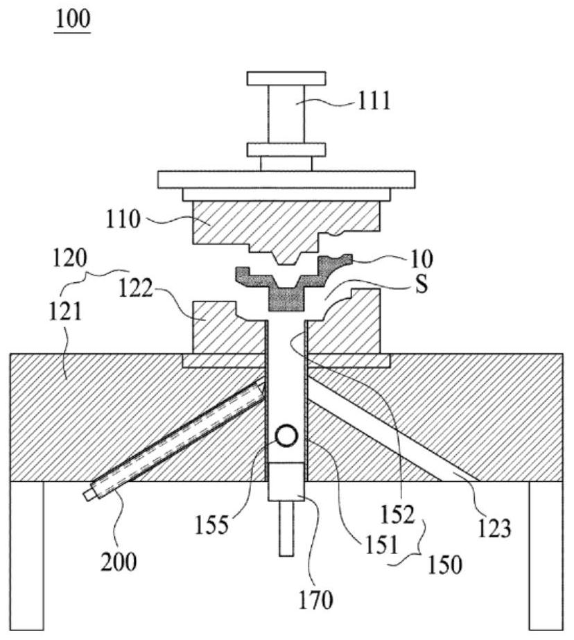
[0037] figure 1 is a sectional view of a die casting apparatus according to a first embodiment of the present invention, and as shown in the figure, a die casting apparatus 100 according to this embodiment includes a movable die 110 and a lower fixed die 120 .

[0038] At this time, the movable mold 110 is provided with a separate moving member 111 at the upper portion to move the movab...


PUM


Abstract

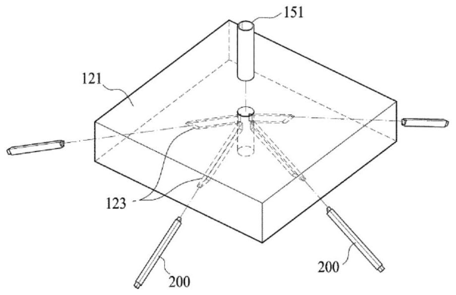
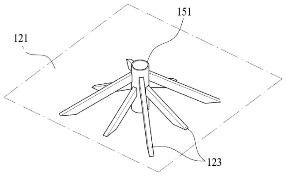
The present invention relates to a die casting apparatus and, more specifically, to a die casting apparatus in which a movable electromagnetically controlled structure control module, which can be withdrawn to the outside, is provided adjacent to a sleeve. The die casting apparatus (100) provided with the movable electromagnetically controlled structure control module (200) comprises a movable die (110) provided with a forming space (S); and a lower fixed die (120) which corresponds to the movable die and accommodates molten metal, and includes a sleeve (150) into which the molten metal is injected, wherein the molten metal is cast into a formed object by bringing the movable die and the lower fixed die into contact with each other. The die casting apparatus is provided with the movable electromagnetically controlled structure control module (200) including at least one electromagnetic stirring device-accommodating part (123) that accommodates an electromagnetic stirring device therein and is configured to pass through the lower fixed die to the vicinity of the sleeve in order to electromagnetically stir the molten metal injected through the sleeve.

Description

technical field [0001] The present invention relates to a die casting device, and more particularly, to a die casting device having a movable electromagnetically controlled tissue control module that can be withdrawn to the outside to be adjacent a sleeve. Background technique [0002] The die-casting device consists of a mold made of a movable mold and a fixed mold, and a sleeve connected to the inside of the mold to form an injection path for molten metal. When the movable mold and the fixed mold are in contact with each other, a molding space is formed, and a molded product can be manufactured by pushing molten metal in the sleeve into the molding space with a plunger and pressing it into a molded part. [0003] As a method of controlling the structure using an electromagnetic field in such a die-casting device, the technique of controlling the structure during the process of injecting molten metal into the sleeve (Korean Patent No. 10-0554093, Korean Patent No. 10-043611...

Claims


Application Information

Patent Timeline
Patent Type & Authority Applications(China)
IPC IPC(8): B22D17/30B22D17/20
CPCB22D17/2023B22D17/2038B22D17/30B22D17/2015B22D17/32
Inventor 朴泰润
Owner FUTURECAST
Learn More