Split-phase output fast switching circuit and surge current suppression control method adopted by same

A fast switching and phase separation technology, which is applied in the direction of circuit devices, AC network circuits, electrical components, etc., can solve problems such as asynchronous switching, autotransformer surge current, abnormal output voltage, etc., to avoid output voltage and improve system Reliability, the effect of avoiding abnormal damage to the load

Pending Publication Date: 2021-06-11
JIANGSU GOODWE POWER SUPPLY TECHNOLOGY CO LTD
View PDF0 Cites 0 Cited by
  • Summary
  • Abstract
  • Description
  • Claims
  • Application Information

AI Technical Summary

Problems solved by technology

[0005] 1. The switch is not synchronized, and the abnormal switch failure leads to abnormal output voltage, damage to the load or shortened service life;
[0006] 2. On-grid and off-grid switching time prolongs, and the load will be powered off;
[0007] 3. Autotransformer surge current problem at the moment of switch closing

Method used


Image

  • Split-phase output fast switching circuit and surge current suppression control method adopted by same
  • Split-phase output fast switching circuit and surge current suppression control method adopted by same
  • Split-phase output fast switching circuit and surge current suppression control method adopted by same

Examples


Embodiment 1

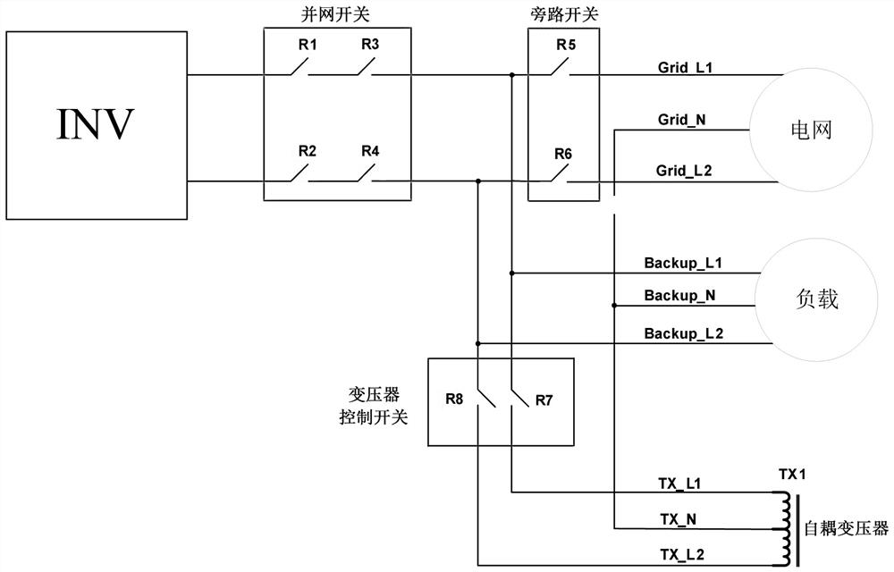
[0030] Embodiment one: as attached figure 2 As shown, a split-phase output fast switching circuit, including (photovoltaic energy storage) inverter INV, grid-connected switch array, bypass switch array, off-grid and transformer synchronous switch array, grid, load and autotransformer TX1. The inverter INV has two live wires L1, L2 and one neutral wire N output, and each live wire and neutral wire is divided into three branches for connecting the power grid, the load and the autotransformer TX1 respectively. The input side of the grid-connected switch array is connected to the output of the inverter INV, and the grid is connected to the output side of the grid-connected switch array. The grid is located on the first branch of each live wire, and the input ports of the grid are Grid_L1 and Grid_N respectively. , Grid_L2. The input side of the bypass switch array is connected to the output side of the grid-connected switch array, the input side of the off-grid and transformer s...


PUM


Abstract

The invention relates to a split-phase output fast switching circuit and a surge current suppression control method adopted by the same. The split-phase output fast switching circuit comprises an inverter, a grid-connected switch array, a power grid, a bypass switch array, a load, an autotransformer and an off-grid and transformer synchronous switch array, wherein an input side of the grid-connected switch array is connected with the inverter, the power grid is connected with an output side of the grid-connected switch array, the bypass switch array is connected with an output side of the grid-connected switch array, the off-grid and transformer synchronous switch array is connected with the inverter, a first output side of the off-grid and transformer synchronous switch array and an output side of the bypass switch array are jointly connected with the load, and a second output side of the off-grid and transformer synchronous switch array is connected with the autotransformer. The surge current suppression control method adopted by the split-phase output fast switching circuit comprises the step of controlling each switch array and controlling the off-grid output voltage of the inverter. According to the split-phase output fast switching circuit and the surge current suppression control method, the reliability of the system can be improved, and fast switching between grid connection and off-grid and uninterrupted power supply of the load can be realized.

Description

technical field [0001] The invention belongs to the technical field of power electronic inverters, and specifically relates to an inverter using an autotransformer to realize off-grid split-phase output, and a switch array to realize a split-phase output fast switching circuit for fast switching between grid-connected and off-grid, and the The control method for suppressing the inrush current adopted by the split-phase output fast switching circuit. Background technique [0002] In some countries and regions, there is a 240 / 120V single-phase three-wire system in the power grid, that is, two live wires L1, L2, and one neutral wire N, called the Split Phase grid, where the photovoltaic energy storage hybrid inverter can realize grid-connected and off-grid There are two working modes of the network. Grid-connected work only needs to output the current of two live wires, L1 and L2, and realize the unbalanced current of L1N and L2N through the transformer at the grid end. Howev...

Claims


Application Information

Patent Timeline
Patent Type & Authority Applications(China)
IPC IPC(8): H02J3/00
CPCH02J3/0073
Inventor 许金韡黄敏方刚卢进军刘滔
Owner JIANGSU GOODWE POWER SUPPLY TECHNOLOGY CO LTD
Why Eureka
Try Eureka