Premixed gas rotational flow combustion test device and method suitable for optical diagnosis

A combustion test and optical diagnosis technology, which is applied in combustion methods, gas fuel burners, burners, etc., can solve problems such as scattering, flow field influence, and flame image distortion, and achieve enhanced gas mixing, avoiding overheating, and reliable ignition Effect

Pending Publication Date: 2021-06-11
清启动力(北京)科技有限公司
View PDF0 Cites 5 Cited by
  • Summary
  • Abstract
  • Description
  • Claims
  • Application Information

AI Technical Summary

Problems solved by technology

[0003] When carrying out premixed gas swirling combustion experiments at home and abroad, circular cross-section combustion chambers are mostly used. This will make the curved quartz glass change the direction of light propagation and may scatter when the flame is optically measured, making the flame image Distortion occurs; in the square combustion chamber designed by some foreign researchers, the quartz glass window is small, and the whole picture of the flame cannot be observed, and the quartz glass is not completely flush with the wall, which has a great impact on the flow field

Method used


Image

  • Premixed gas rotational flow combustion test device and method suitable for optical diagnosis
  • Premixed gas rotational flow combustion test device and method suitable for optical diagnosis
  • Premixed gas rotational flow combustion test device and method suitable for optical diagnosis

Examples


Embodiment Construction

[0032] The present invention proposes a premixed gas swirling combustion test device and method suitable for optical diagnosis. The present invention will be further described below in conjunction with the accompanying drawings and specific embodiments.

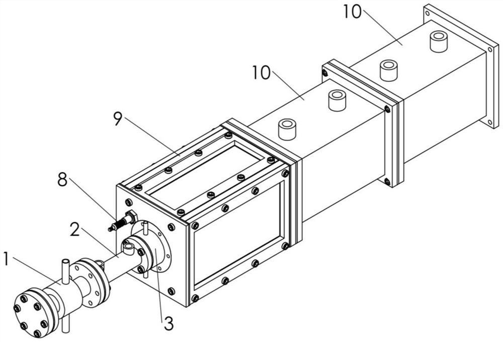
[0033] A premixed gas swirling combustion test device suitable for optical diagnosis, including an intake assembly, a combustion chamber observation section, and a combustion chamber extension section.

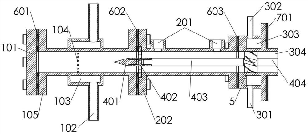
[0034] Such as figure 1 As shown, the air intake assembly includes an air intake section 1, a transition measurement section 2, and a cooling and heat insulation section 3, and the inner passage sections of these three sections are circular. Such as figure 2 As shown, the head cover plate 101 of the air inlet section is located at the head of the air inlet passage, and is connected to the connecting flange 105 of the air inlet section by screws, and the first PTFE gasket 601 is pressed to achieve sealing. Fuel and air ente...


PUM


Abstract

The invention discloses a premixed gas rotational flow combustion test device and method suitable for optical diagnosis, and belongs to the technical field of transparent combustion chamber design. The device comprises an air inlet assembly, a combustion chamber observation section and a combustion chamber extension section. The gas inlet assembly comprises a gas inlet section, a transition measurement section, a cooling heat insulation section, a swirler and a central column, gas enters a circular gas inlet channel from a gas collection cavity through small holes densely distributed in the circumferential direction, enters an annular gas inlet channel through the tip end of the central column, and then flows through the swirler to generate rotational flow; the combustion chamber observation section comprises quartz glass, a sealing gasket, an observation window cover plate and the like; gas is ignited by a spark plug to generate rotational flow flame after being injected into the combustion chamber; the combustion chamber extension section comprises a pressure sensor mounting seat, a thermocouple mounting seat and a connecting flange, and combustion products are discharged out of the combustion chamber from an outlet of the combustion chamber extension section. According to the device, central columns with different lengths and cyclones with different blade angles can be replaced conveniently, the air inlet channel section is prevented from being overheated, flame and flow field information can be captured conveniently, and optical diagnosis of rotational flow flame is achieved.

Description

technical field [0001] The invention relates to the technical field of transparent combustion chamber design, in particular to a premixed gas swirl combustion test device and method suitable for optical diagnosis. Background technique [0002] Various types of burners in aero-engines, ground gas turbines, and industrial furnaces are widely used in swirling flame stabilization. Before the burner is applied, a large number of tests need to be carried out in the model combustion chamber to investigate the flow field structure, flame surface shape, and combustion stability of the swirling flame. The traditional model combustion chamber cannot directly observe and measure the swirling flame, and cannot obtain the flow field and flame structure in the combustion chamber, which limits researchers' understanding of the stability mechanism of swirling combustion. Domestic and foreign studies have shown that parameters such as intake thermal conditions, swirler structure, swirler pos...

Claims


Application Information

Patent Timeline
Patent Type & Authority Applications(China)
IPC IPC(8): G01M99/00G01P5/20G01N21/84G01N21/64F23R3/58F23Q3/00F23D14/78F23D14/70F23D14/62F23D14/46
CPCG01M99/00G01P5/20G01N21/84G01N21/6402F23D14/46F23D14/78F23D14/62F23D14/70F23Q3/006F23R3/58G01N2021/8411
Inventor 王兵饶珠明李睿超谢峤峰范文琦
Owner 清启动力(北京)科技有限公司
Why Eureka
Try Eureka