


Quick Research
Generate reliable direction feasibility study reports for your R&D in just a few steps.

Technical Q&A
Discover and master advanced knowledge NOW. Basics, ideas, possibilities, all at once.

Find Solutions
As an expert in R&D theories, this can generate solutions to your technical problems instantly.

Evaluate Feasibility
Analyze your overall solution with one click, know your potential R&D risks in advance.

Monitor Landscape
Get weekly tech updates, stay abreast of the latest tech innovations and key insights.
Operation safety improving device for construction machinery
A technology for construction machinery and safety, which is applied in the direction of mechanical equipment, supporting machines, machine platforms/supports, etc., can solve problems such as difficult to obtain guarantees, and achieve the effects of easy adjustment, easy monitoring operations, and guaranteed monitoring range
- Summary
- Abstract
- Description
- Claims
- Application Information
AI Technical Summary
Problems solved by technology
Method used
Image

Examples
Embodiment 1
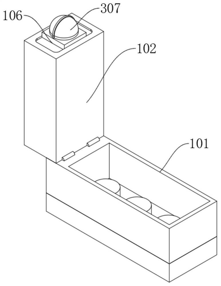
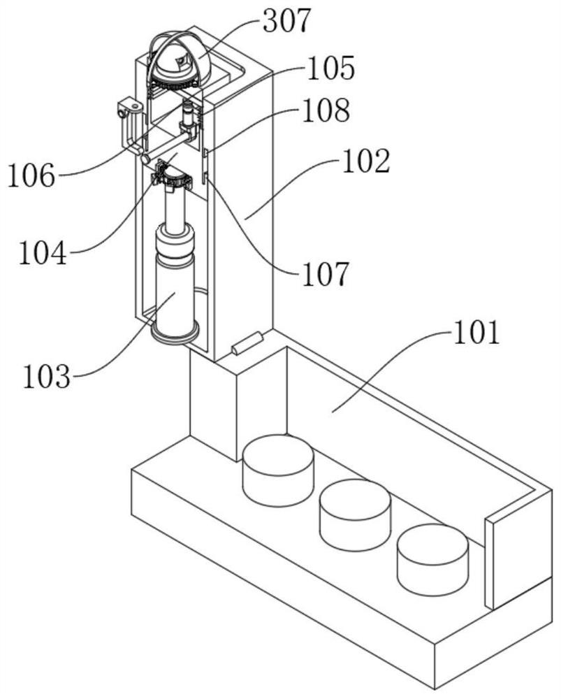
[0027] refer to Figure 1-5 , an operation safety improving device for a construction machine, comprising: a suction mounting case 101 and a rotating case 102, the suction mounting case 101 is suction mounted at the start button, the left side of the suction mounting case 101 is connected to the lower end of the rotating case 102 Via a hinge connection, a hydraulic telescopic rod 103 is fixedly installed inside the rotating housing 102, and the upper end of the hydraulic telescopic rod 103 is fixedly connected with the middle part of the lower end of the mobile rotating housing 104. The upper end is fixedly connected with the lower end of the telescopic shell 105, the upper end of the telescopic shell 105 is fixedly connected with the lower surface of the fixed base 106, the upper surface of the fixed base 106 is fixedly installed with a rotating self-cleaning monitoring mechanism, and the upper end of the hydraulic telescopic rod 103 is connected with the lower end of the mobi...
Embodiment 2
[0031] Embodiment 2: Based on Embodiment 1, but different again is;
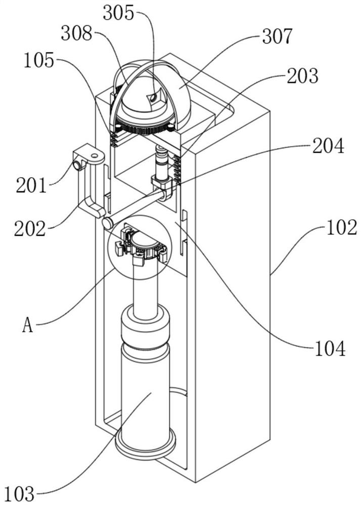
[0032] The mobile steering mechanism includes: a steering knuckle 201, a supporting column 202, a rotating hydraulic rod 203 and a supporting shaft 204. The front and rear sides of the inner bottom surface of the mobile rotating housing 104 are fixedly equipped with supporting columns 202. The upper end of the supporting column 202 passes through the rotating shaft and the lower end of the steering knuckle 201. Flexible connection, the upper end of the steering knuckle 201 is fixedly connected with the front and rear sides on the left side of the lower surface of the fixed base 106, and the support shaft 204 is fixedly installed on the lower right side inside the moving and rotating housing 104, and the upper middle part of the support shaft 204 is connected with the axis center of the lower end of the rotating hydraulic rod 203 Flexible connection, the upper end of the rotating hydraulic rod 203 is fixedly c...
Embodiment 3
[0034] Embodiment 3: based on Embodiment 1 and 2, but different again is;
[0035] The rotating self-cleaning monitoring mechanism includes: a servo motor 301, a main gear 302, a differential gear 303, a rotating gear ring 304, and a monitoring camera 305. A servo motor 301 is fixedly installed inside the fixed base 106, and a main shaft is fixedly installed on the upper end of the servo motor 301 main shaft. Gear 302, three groups of differential gears 303 are arranged around the main gear 302, the outer side of the differential gear 303 meshes with the inner wall of the rotating gear ring 304, and the upper surface of the rotating gear ring 304 is fixedly connected with the lower surface of the monitoring camera 305.
[0036] The outer wall of the rotating gear ring 304 is meshed with the transmission gear 306. A transparent protective cover 307 is arranged around the outer side of the transmission gear 306. The bottom edge of the transparent protective cover 307 is also rota...
PUM
 Abstract
Description
Claims
Application Information
 - R&D Engineer
- R&D Manager
- IP Professional
- Industry Leading Data Capabilities
- Powerful AI technology
- Patent DNA Extraction
Browse by: Latest US Patents, China's latest patents, Technical Efficacy Thesaurus, Application Domain, Technology Topic, Popular Technical Reports.
© 2024 PatSnap. All rights reserved.Legal|Privacy policy|Modern Slavery Act Transparency Statement|Sitemap|About US| Contact US: help@patsnap.com