Injection molding mold for dosing injection part of infusion apparatus

A technology of injection molding and injection parts, which is applied in the field of medical devices, can solve the problems such as the inability to discharge air bubbles, and achieve the effects of long service life, high efficiency, and smooth and beautiful appearance of products.

Pending Publication Date: 2021-06-11
JIANGXI HONGDA MEDICAL EQUIP GROUP
View PDF0 Cites 0 Cited by
  • Summary
  • Abstract
  • Description
  • Claims
  • Application Information

AI Technical Summary

Problems solved by technology

Since the national standard GB8368-2018 will be implemented in 2021, the standard requires that the Mufei dropper cannot be used for dosing, so the dosing port of most infusion sets on the market can only be set at the Y-shaped dosing injection part at the end of the infusion set On the other hand, the Y-type dosing injection has disadvantages during the use of the infusion set, especially before the infusion, the air bubbles cannot be completely discharged during the exhaust process of the infusion set

Method used


Image

  • Injection molding mold for dosing injection part of infusion apparatus
  • Injection molding mold for dosing injection part of infusion apparatus
  • Injection molding mold for dosing injection part of infusion apparatus

Examples


Embodiment 1

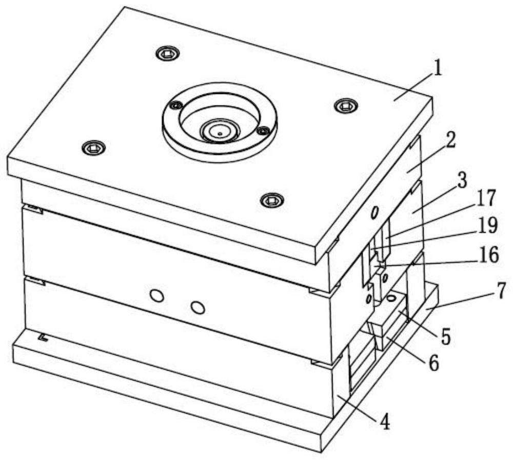
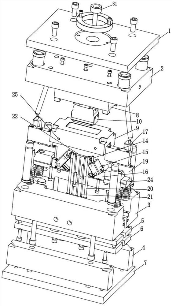
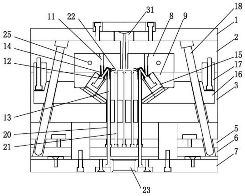
[0036] see Figure 1 to Figure 4 , an injection molding mold for injection parts of infusion sets provided in an embodiment of the present invention, including an upper fixing plate 1, a female template 2, a male template 3, and two mold feet arranged in sequence from top to bottom 4 and the lower fixing plate 7, an upper ejector plate 5 and a lower ejector plate 6 are stacked between the two mold feet 4, the upper ejector plate 5 and the lower ejector plate 6 are fixed as one, and can be fixed on the lower Move up and down between the board 7 and the male template 3;

[0037] The bottom of the female template 2 is provided with a first injection molding assembly set downwards, the male template 3 is provided with a second injection molding assembly arranged obliquely upwards, and the lower fixing plate 6 is provided with a third injection molding assembly set upwards. assembly, the end of the third injection molding assembly is in close contact with the end of the second inj...

Embodiment 2

[0060] see Figure 5 and Figure 6 , in this embodiment, the end face of the male template 3 is provided with a spacer 26, and the spacer 26 is provided with an oil cylinder 27, and the end of the piston rod of the oil cylinder 27 passes through the spacer 26 and the spacer. The slider seat 16 is connected, that is, the sliding of the slider seat 16 is realized by an oil cylinder 27 .

[0061] Specifically, in this embodiment, since the movement stroke of the oil cylinder 27 can be very large, the movement stroke of the slider seat 16 can be adjusted by directly adjusting the oil cylinder 27 or replacing the oil cylinder 27, and the non-oil cylinder structure needs to be re-modified and processed many mold parts. Accessories; through the oil cylinder 27, it is more convenient to control the time and direction of the movement of the slider seat 16 (such as directly adjusting the installation direction of the oil cylinder 27), instead of the oil cylinder structure, various obli...

Embodiment 3

[0071] see Figure 7 , in this embodiment, a male mold carrier plate 28 is provided between the male template 3 and the upper ejector plate 5, and the bundle block 17a is fixed in the through hole of the male mold carrier plate 28, and the male mold carrier plate The angle pin 18a that is arranged obliquely upward is provided with in the oblique hole of 28;

[0072] The bottom of the female template 2 is provided with a shutter 29, and the bottom of the shutter 29 extends into the male template 3, and the shutter 29 is used to control the order of opening between each template when the mold is opened. When the mold is opened, the male template 3 and the female template 2 are pulled, so that the female template 2 drives the male template 3 to move, so that the gap between the male template 3 and the male mold carrier plate 28 is opened first, and the male mold carrier plate 28 drives the beam block 17a and the slider The insert 15a is separated, and at the same time, the corne...


PUM


Abstract

The invention discloses an injection molding mold for a dosing injection part of an infusion apparatus. The injection molding mold comprises an upper fixed plate, a cavity plate, a core plate, two mold feet and a lower fixed plate, wherein an upper ejection plate and a lower ejection plate are arranged between the two mold feet in a stacked mode; a first injection molding component is arranged at the bottom of the cavity plate, a second injection molding component is arranged on the core plate, a third injection molding component is arranged on the lower fixed plate, and a product cavity is formed among the first injection molding component, the second injection molding component and the third injection molding component; and a runner is arranged between the cavity plate and the core plate, a glue injection bushing which extends downwards and is communicated with the runner is arranged in the upper fixed plate, a runner ejector pin is fixed on the upper ejector plate, and the end part of the runner is communicated with the product cavity. According to the injection-molded dosing injection part of the infusion apparatus in the technical scheme, no bubble remains in the using process, clinical operation is facilitated, infusion safety of a patient is guaranteed, meanwhile, the runner and a product are automatically separated in the production process, the product is smooth and attractive in appearance, and the mold can achieve automatic production and is small in size, high in efficiency and long in service life.

Description

technical field [0001] The invention relates to the technical field of medical devices, in particular to an injection molding mold for a drug-dosing injection part of an infusion set. Background technique [0002] The infusion set is mainly used for clinical intravenous infusion treatment for patients with diseases. When the liquid medicine needs to be added during the infusion process, most of the traditional infusion sets are provided with a medicine filling port above the Mufei's dripping funnel. Since the national standard GB8368-2018 will be implemented in 2021, the standard requires that the Mufei dropper cannot be used for dosing, so the dosing port of most infusion sets on the market can only be set at the Y-shaped dosing injection part at the end of the infusion set On the other hand, the Y-type drug dosing injection has disadvantages during the use of the infusion set, especially before the infusion, the air bubbles cannot be completely discharged during the exhaus...

Claims


Application Information

Patent Timeline
Patent Type & Authority Applications(China)
IPC IPC(8): B29C45/73B29C45/40B29C45/27
CPCB29C45/2711B29C45/401B29C45/7312
Inventor 简玉梅邱博梅绍伟杨剑卫彦伟
Owner JIANGXI HONGDA MEDICAL EQUIP GROUP
Why Eureka
Try Eureka