
Clamping and fixing device for intelligent manufacturing hardware machining equipment

A processing equipment and clamping and fixing technology, which is applied in the field of clamping and fixing devices for intelligent manufacturing hardware processing equipment, can solve the problems of workpiece damage, increased labor, limited application range, etc., and achieve the effect of preventing loosening and avoiding workpiece deviation

Inactive Publication Date: 2021-06-11
甘肃三只羊农林机械有限公司
View PDF9 Cites 2 Cited by
  • Summary
  • Abstract
  • Description
  • Claims
  • Application Information

AI Technical Summary

Problems solved by technology

The mechanical equipment used for metal processing includes CNC lathes, milling machines, boring machines, and drilling machines. When processing hardware workpieces, they need to be clamped and fixed first. Existing processing equipment generally manually adjusts the clamping device to adjust the workpiece. Clamping and fixing not only increases the amount of labor, but also the operation is more complicated and not convenient enough; general automatic clamping devices can only clamp and fix workpieces with regular shapes, so the scope of application is limited, and the practicability needs to be improved, and The general automatic clamping device cannot automatically stop running after clamping the workpiece, and requires manual operation control. Not only is the degree of automation not high enough, but also excessive clamping may occur, causing damage to the workpiece
[0003] Aiming at the deficiencies of the prior art, the present invention provides a clamping and fixing device for intelligent manufacturing hardware processing equipment, which has the advantages of being suitable for workpieces of various shapes, preventing excessive clamping, and more stable clamping, and solves the problem of general clamping The degree of automation of the holding fixture is not high enough and the scope of application is limited

Method used


Image

  • Clamping and fixing device for intelligent manufacturing hardware machining equipment
  • Clamping and fixing device for intelligent manufacturing hardware machining equipment
  • Clamping and fixing device for intelligent manufacturing hardware machining equipment

Examples


Embodiment Construction

[0023] The following will clearly and completely describe the technical solutions in the embodiments of the present invention with reference to the accompanying drawings in the embodiments of the present invention. Obviously, the described embodiments are only some, not all, embodiments of the present invention. Based on the embodiments of the present invention, all other embodiments obtained by persons of ordinary skill in the art without making creative efforts belong to the protection scope of the present invention.

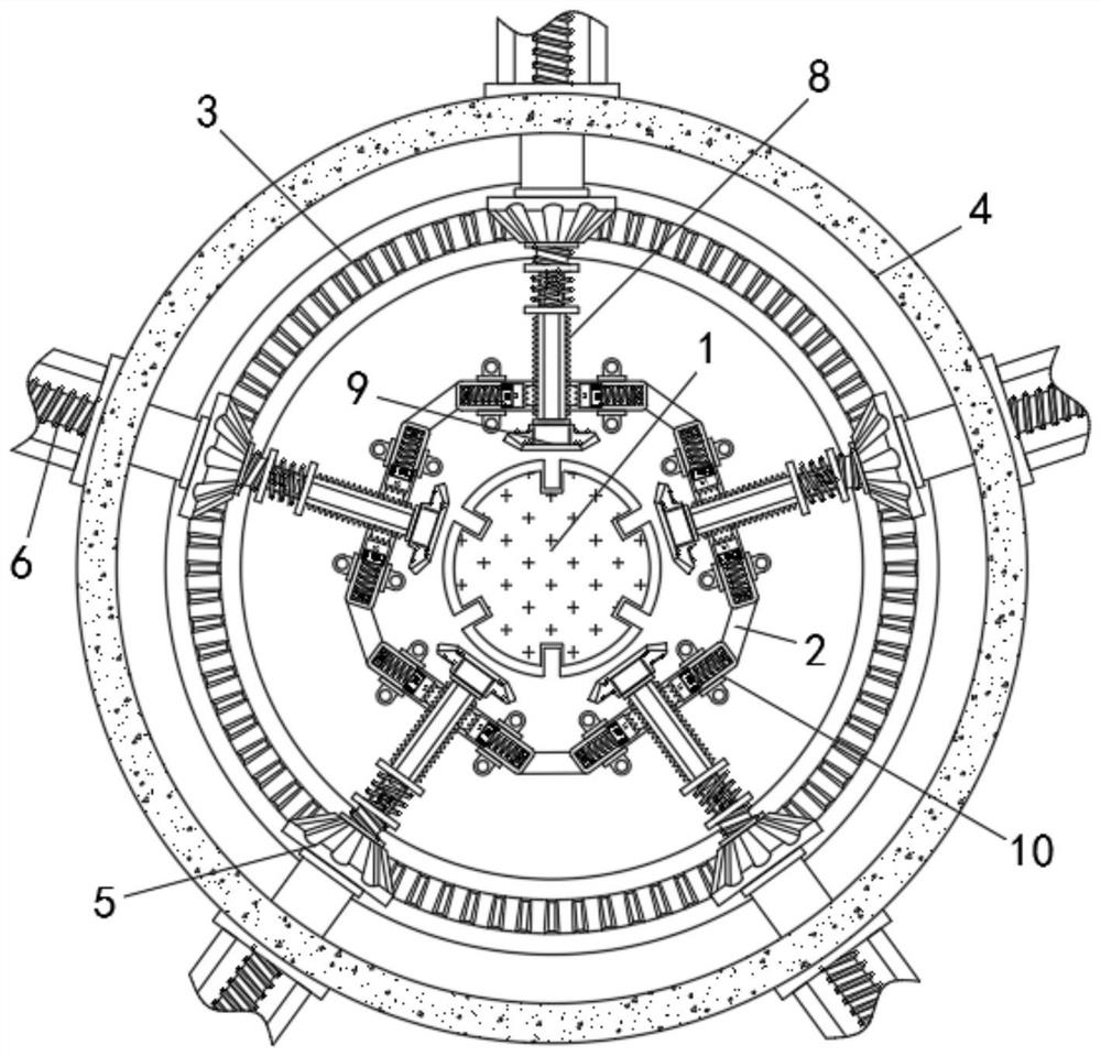
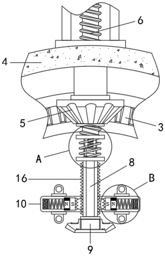
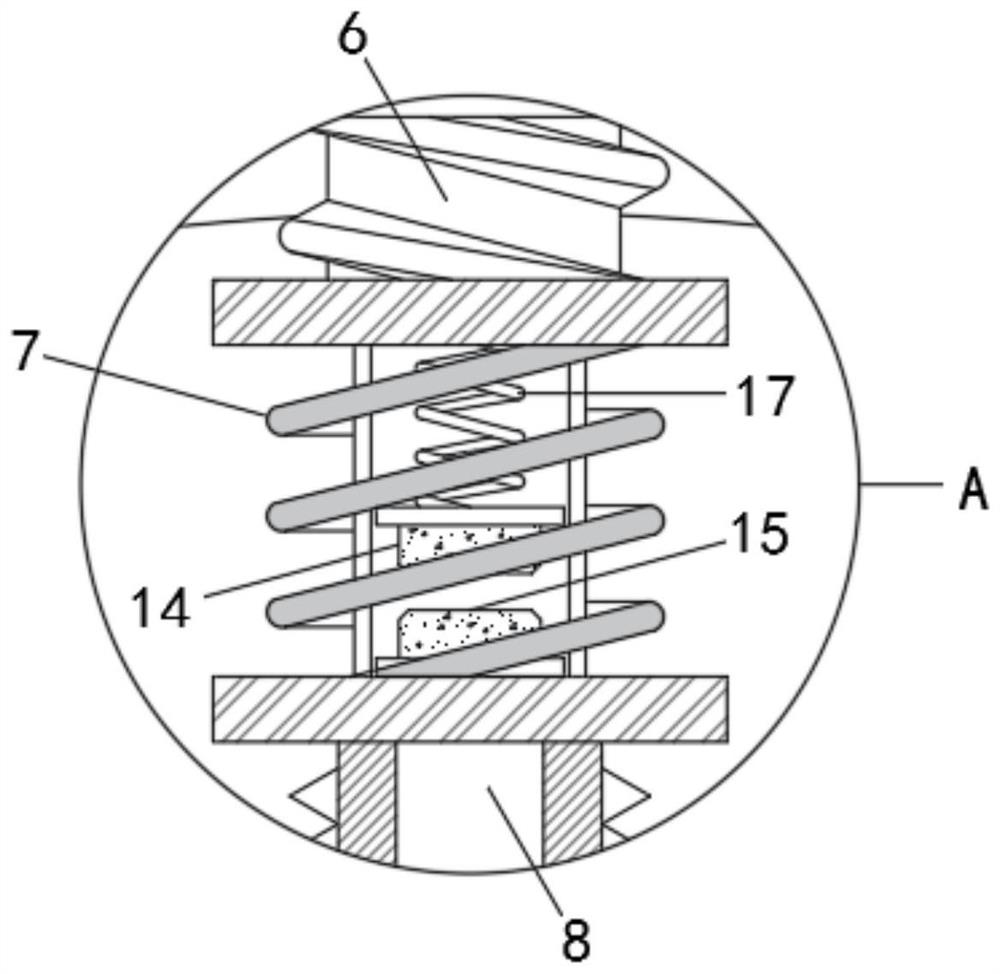
[0024] see Figure 1-4 , a clamping and fixing device for intelligent manufacturing hardware processing equipment, including a placement plate 1, a mounting bracket 2 is provided on the outside of the placement plate 1, a ring gear 3 is provided on the outside of the mounting bracket 2, and a ring frame is provided on the outside of the ring gear 3 4. There are bevel gears 5 connected to the inner ring of the ring frame 4 in rotation. There are five bevel gear...


PUM


Abstract

The invention relates to the technical field of hardware mechanical equipment, and discloses a clamping and fixing device for intelligent manufacturing hardware machining equipment. The device comprises a placing disc, a mounting bracket is arranged at the outer side of the placing disc, a gear ring is arranged at the outer side of the mounting bracket, and an annular frame is arranged at the outer side of the gear ring. The inner ring of the annular frame is rotationally connected with a bevel gear, and the axis of the bevel gear is in threaded connection with a threaded rod. According to the clamping and fixing device for the intelligent manufacturing hardware machining equipment, after two contact blocks abut against each other, the electrified magnetism of an electromagnet is enhanced, the magnetism of the ends, close to each other, of a magnet block and the electromagnet is the same, the electromagnet drives the magnet block to move in the direction close to a guide rod, finally the magnet block abuts against the guide rod, sawteeth at the ends, close to each other, of the magnet block and the guide rod are meshed with each other, the guide rod is squeezed by the magnet block and limited by the sawteeth and cannot move easily, a clamp holder is prevented from loosening in the machining process, workpiece deviation is avoided, and the clamping and fixing stability is improved.

Description

technical field [0001] The invention relates to the technical field of hardware machinery equipment, in particular to a clamping and fixing device for intelligent manufacturing hardware processing equipment. Background technique [0002] Traditional hardware products refer to five metals including gold, silver, copper, iron, and tin, which can be machined into knives, swords and other works of art or metal devices. The mechanical equipment used for metal processing includes CNC lathes, milling machines, boring machines, and drilling machines. When processing hardware workpieces, they need to be clamped and fixed first. Existing processing equipment generally manually adjusts the clamping device to adjust the workpiece. Clamping and fixing not only increases the amount of labor, but also the operation is more complicated and not convenient enough; general automatic clamping devices can only clamp and fix workpieces with regular shapes, so the scope of application is limited, ...

Claims


Application Information

Patent Timeline
Patent Type & Authority Applications(China)
IPC IPC(8): B23Q3/06B23Q3/154
CPCB23Q3/06B23Q3/1543
Inventor 张辉
Owner 甘肃三只羊农林机械有限公司
Learn More