A power-on control circuit and related device

A power-on control and circuit technology, applied in computer control, program control, general control system, etc., can solve the problems of chip leakage, complicated circuit structure design, etc., and achieve the effect of fast switching of the machine

Active Publication Date: 2022-07-19
BEIJING SPREADTRUM HI TECH COMM TECH CO LTD
View PDF6 Cites 0 Cited by
  • Summary
  • Abstract
  • Description
  • Claims
  • Application Information

AI Technical Summary

Problems solved by technology

[0004] However, the above-mentioned method of grounding the power-on control pin of the chip will cause the problem of electric leakage after the chip is automatically powered on, and the above-mentioned method of controlling the automatic power-on or shutdown of the chip through the MCU will lead to complicated circuit structure design.

Method used


Image

  • A power-on control circuit and related device
  • A power-on control circuit and related device
  • A power-on control circuit and related device

Examples


Embodiment Construction

[0054] The technical solutions in the embodiments of the present application will be clearly and completely described below with reference to the accompanying drawings in the embodiments of the present application. Obviously, the described embodiments are some, but not all, embodiments of the present application.

[0055] Embodiments of the present application provide a power-on control circuit and a related device, which will be described in detail below.

[0056] The terms "first", "second", etc. involved in the embodiments of the present application are used to distinguish different objects, rather than to describe a specific order. In addition, the terms "include" and "have" and any of their modifications are intended to be Override non-exclusive includes.

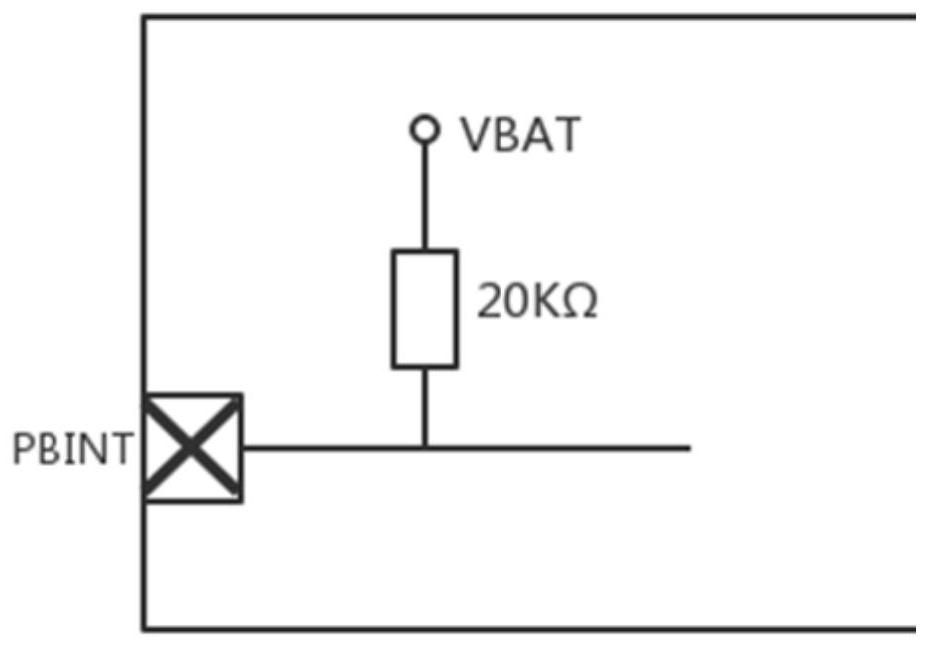
[0057] see figure 1 , figure 1 It is a schematic structural diagram of an on-board circuit of a power-on control pin disclosed in an embodiment of the present application. like figure 1 As shown, the power-on cont...


PUM


Abstract

The embodiments of the present application disclose a power-on control circuit and a related device. The circuit includes: a power-on control unit and an anti-leakage circuit; a first port of the power-on control unit is connected to a power-on control pin of a chip, and a second port of the power-on control unit is connected to a power-on control pin of a chip. Grounding, the third port of the power-on control unit is connected to the first port of the anti-leakage circuit, the second port of the anti-leakage circuit is connected to the power supply, and the third port of the anti-leakage circuit is grounded; the power-on control unit is used to receive the power-on sent by the anti-leakage circuit After receiving the signal, the level of the power-on control pin is controlled to realize the function of the chip automatically turning on. By implementing the embodiments of the present application, through the power-on control unit and the anti-leakage circuit, the functions of the chip can be automatically turned on, off, and anti-leakage, and the circuit design is greatly simplified, and the circuit use efficiency is improved.

Description

technical field [0001] The present application relates to the technical field of electronic circuits, and in particular, to a power-on control circuit and related devices. Background technique [0002] With the development of digital control technology in the field of electronic circuits, more and more occasions require automatic startup or shutdown control of equipment, especially for communication equipment or circuits with high energy consumption, such as a large number of 5G base stations arranged in 5G mobile communications , so that the energy consumption of 5G network increases exponentially. Therefore, it has become a common method to reduce energy consumption to automatically start or shut down the equipment. [0003] At present, the general boot control method is to ground the boot control pin of the chip to achieve the purpose of automatically booting after power-on, or connect the boot control pin of the chip to the general transmission interface of the micro co...

Claims


Application Information

Patent Timeline
Patent Type & Authority Patents(China)
IPC IPC(8): G05B19/042
CPCG05B19/0423G05B2219/25257
Inventor 李淼刘洋
Owner BEIJING SPREADTRUM HI TECH COMM TECH CO LTD
Why Eureka
Try Eureka