
Humidifying device of air conditioning equipment

A technology for air-conditioning equipment and humidification devices, which is applied in air humidification systems, air-conditioning systems, lighting and heating equipment, etc., and can solve problems such as the influence of air output, the humidification device has no filter mechanism, and the humidification range is limited.

Inactive Publication Date: 2021-06-08
张俊辉
View PDF0 Cites 1 Cited by
  • Summary
  • Abstract
  • Description
  • Claims
  • Application Information

AI Technical Summary

Problems solved by technology

[0003] At present, the humidifying device of the existing air-conditioning equipment uses a circulating water tank to cooperate with the wet film for humidification, but the setting of the wet film causes the air output to be affected, and the humidification range is limited. At the same time, the water tank will generate scale after long-term use, and The humidifier does not have a filter mechanism, and the wet film is easy to attach dust and affect the use

Method used


Image

  • Humidifying device of air conditioning equipment
  • Humidifying device of air conditioning equipment
  • Humidifying device of air conditioning equipment

Examples


Embodiment Construction

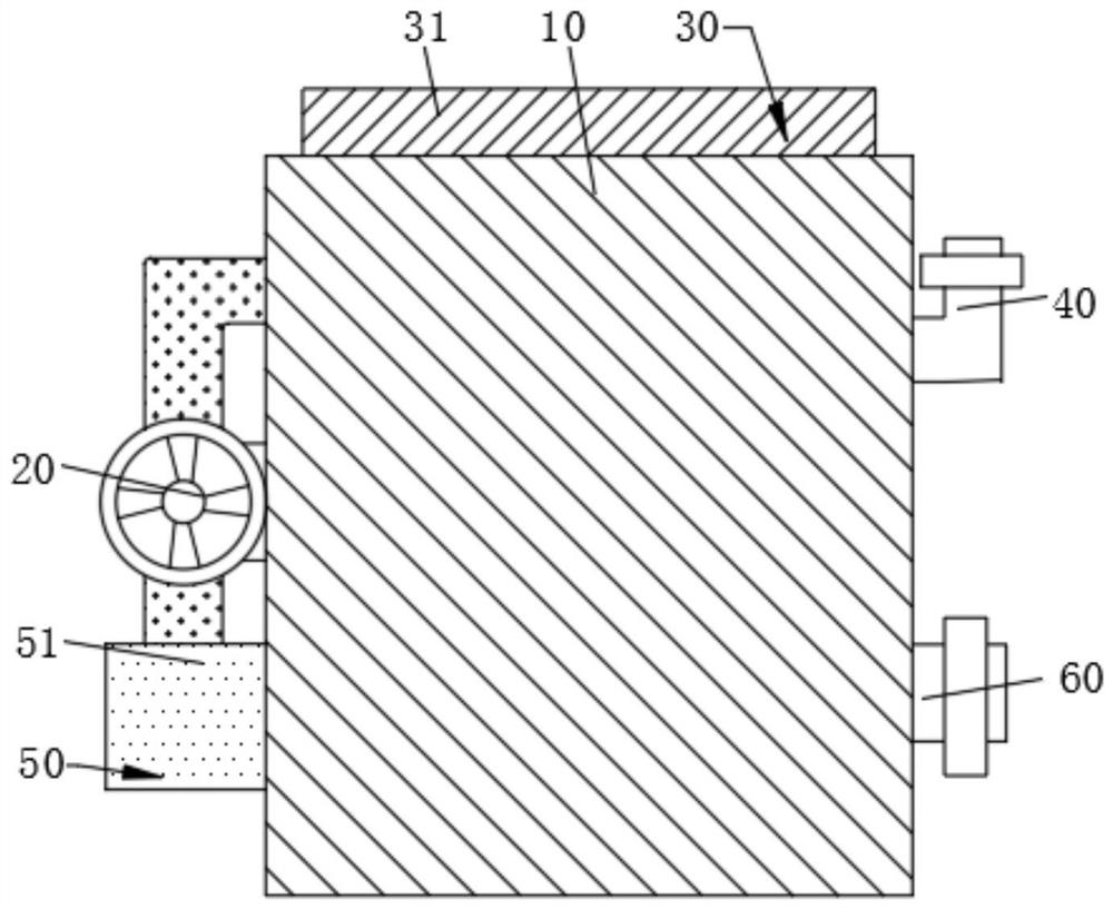
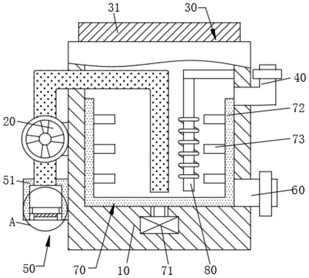
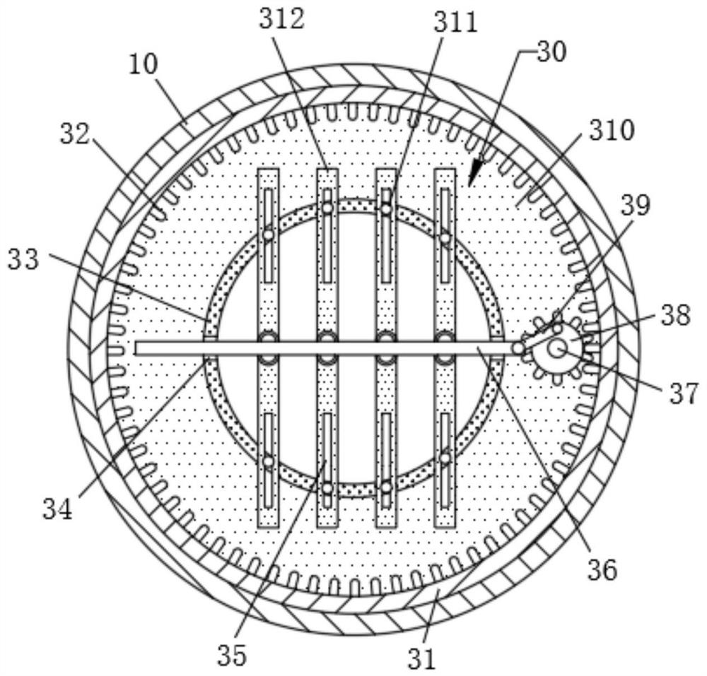
[0017] see Figure 1-Figure 4 , the humidifying device of air-conditioning equipment, including a water tank 10, the water tank 10 is provided with an air outlet assembly 30, the side of the water tank 10 is provided with a fan 20 and a filter assembly 50, the water tank 10 is provided with a descaling assembly 70, and the air outlet assembly 30 includes a first circle The ring 31 and the second ring 310, the first ring 31 is fixed on the water tank 10, by being provided with the first ring 31, it is convenient to accept the teeth 32, the second ring 310 is rotationally connected with the water tank 10, the first ring The inner wall of 31 is provided with tooth 32, by being provided with tooth 32, is convenient to drive gear ring 38 to rotate, and the first motor 37 is fixedly installed on the second circular ring 310, and the model of the first motor 37 is TCB8024 B3, by being provided with The first motor 37 plays the purpose of driving the gear ring 38 to rotate. The rotati...


PUM


Abstract

The invention discloses a humidifying device of air conditioning equipment. The humidifying device of the air conditioning equipment comprises a water tank, an air outlet assembly is arranged on the water tank, a draught fan and a filtering assembly are arranged on the side face of the water tank, a descaling assembly is arranged in the water tank, the air outlet assembly comprises a first circular ring and a second circular ring, the first circular ring is fixed to the water tank, the second circular ring is rotationally connected with the water tank, the inner wall of the first circular ring is provided with teeth, the second circular ring is fixedly provided with a first motor, the rotating shaft end of the first motor is provided with a gear ring, the gear ring is meshed with the teeth, the inner wall of the second circular ring is provided with an exhaust pipe, the exhaust pipe penetrates through the water tank, the exhaust pipe is provided with limiting pins, the two sides of the exhaust pipe are provided with sliding grooves, the inner walls of the sliding grooves are slidably connected with connecting rods, the connecting rods are rotationally connected with air guide pieces, strip-shaped grooves are formed in the air guide pieces, the limiting pins are slidably connected with the strip-shaped grooves, one ends of the connecting rods are rotationally connected with a rotating rod, and one end of the rotating rod is rotationally connected with a gear ring. By arranging the air outlet assembly, the humidification range is expanded, rapid indoor humidification is facilitated, by arranging the descaling assembly, water scale is reduced, and meanwhile water scale cleaning is facilitated.

Description

technical field [0001] The invention belongs to the technical field of air conditioning, in particular to a humidifying device for air conditioning equipment. Background technique [0002] Air-conditioning equipment refers to equipment that supplies treated air to a designated space to maintain a specified temperature and humidity and control the content of dust and harmful gases, referred to as air-conditioning equipment. [0003] At present, the humidifying device of the existing air-conditioning equipment uses a circulating water tank to cooperate with the wet film for humidification, but the setting of the wet film causes the air output to be affected, and the humidification range is limited. At the same time, the water tank will generate scale after long-term use, and The humidifier does not have a filter mechanism, and the wet film is easy to attach dust and affect the use. Contents of the invention [0004] The purpose of the present invention is to provide a humid...

Claims


Application Information

Patent Timeline
IPC IPC(8): F24F6/06F24F13/28F24F13/06
CPCF24F6/06F24F13/06F24F13/28F24F2221/34
Inventor 张俊辉蒋国彬邵伟
Owner 张俊辉
Learn More