A clutch assembly of a crane power device

A clutch assembly and power device technology, applied in the field of clutches, can solve the problems of burning and deformation of the flywheel and pressure plate, poor heat dissipation of the flywheel and pressure plate, and small shock absorption stroke of the shock-absorbing spring, so as to prevent deformation or even damage, prevent The effect of turning slippage and preventing caustic carbonization damage

Active Publication Date: 2021-07-16
XINXIANG UNIV
View PDF19 Cites 2 Cited by
  • Summary
  • Abstract
  • Description
  • Claims
  • Application Information

AI Technical Summary

Problems solved by technology

[0004] In order to overcome the clutch plate damping device of the existing clutch, it is installed at the center of the clutch plate, which reduces the contact area between the clutch plate, the pressure plate and the flywheel. Due to the limitation of the clutch plate, the damping stroke of the shock absorbing spring is very small. , resulting in poor shock absorption performance. At the start of the crane, the clutch plate is in a semi-linkage state. The flywheel, pressure plate and clutch plate rotate and rub at high speed, which makes the flywheel, pressure plate and clutch plate heat up rapidly, and the flywheel and pressure plate dissipate heat. The flywheel and the pressure plate are burned and deformed, and the high-temperature flywheel and the pressure plate will burn and carbonize the clutch plate, resulting in damage to the clutch plate. The technical problem to be solved is: to provide a fast heat dissipation, increase the contact area of ​​the clutch plate and Clutch assembly of crane power unit with large shock absorbing stroke

Method used


Image

  • A clutch assembly of a crane power device
  • A clutch assembly of a crane power device
  • A clutch assembly of a crane power device

Examples


Embodiment Construction

[0033] In order to make the object, technical solution and advantages of the present invention clearer, the present invention will be further described in detail below in combination with specific embodiments and with reference to the accompanying drawings. It should be understood that these descriptions are exemplary only, and are not intended to limit the scope of the present invention. Also, in the following description, descriptions of well-known structures and techniques are omitted to avoid unnecessarily obscuring the concept of the present invention.

[0034] Preferred embodiment of the present invention:

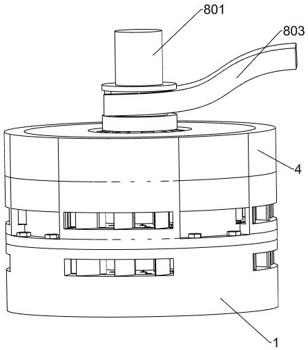
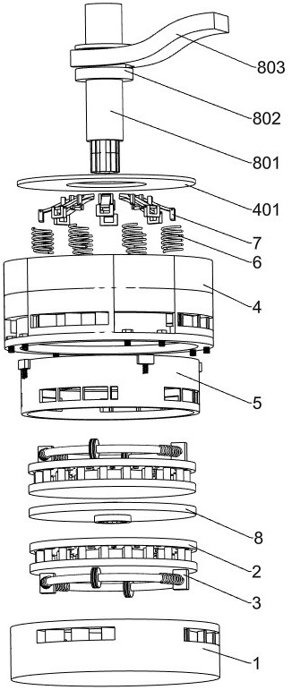
[0035] A clutch assembly of a crane power unit, such as Figure 1-17 As shown, include flywheel 1, friction disc 2, damping mechanism, fixed box 4, round cover 401, bolt 405, extruding mechanism, the 3rd spring 6 and clutch plate 8, friction disc 2 and damping mechanism are respectively arranged as Two, two friction discs 2 and two damping mechanisms are respective...


PUM


Abstract

The invention relates to the field of clutches, in particular to a clutch assembly of a crane power device. The technical problem to be solved is to provide a clutch assembly of a crane power device with rapid heat dissipation, increased contact area of ​​clutch plates and large shock absorbing stroke. The technical embodiment of the present invention is: a clutch assembly of a crane power device, including a flywheel, a friction disc, a shock absorbing mechanism, a fixed box, an extruding mechanism, a third spring and a clutch plate; the extruding mechanism is arranged in the fixed box , the fixed box is fixedly connected with the flywheel, the friction disc and the shock absorbing mechanism are respectively set to two, the flywheel and the extruding mechanism are respectively provided with a friction disc and a shock absorbing mechanism, and the two friction discs are respectively connected to the flywheel and the extruding mechanism in rotation , the two friction discs are fixedly connected with the two shock absorbing mechanisms, and the two friction discs clamp the clutch plate through the pressing force of the third spring on the pressing mechanism. The invention realizes the rotation buffering of the friction disc and the clutch plate through the damping mechanism.

Description

technical field [0001] The invention relates to the field of clutches, in particular to a clutch assembly of a crane power device. Background technique [0002] The clutch is located in the flywheel housing between the engine and the gearbox, and the clutch assembly is fixed on the rear plane of the flywheel with screws, and the output shaft of the clutch is the input shaft of the gearbox. During the driving process of the car, the driver can step on or release the clutch pedal as needed to temporarily separate and gradually engage the engine and the transmission, so as to cut off or transmit the power input from the engine to the transmission. Clutches are common components in mechanical transmissions that can disengage or engage the transmission system at any time. [0003] The existing crane clutch is basically similar to the traditional automobile clutch. Because the crane is a special hoisting machinery, the curb weight of the crane itself is very large. Due to the unc...

Claims


Application Information

Patent Timeline
Patent Type & Authority Patents(China)
IPC IPC(8): F16D25/12F16D25/0638F16F15/067
CPCF16D25/0638F16D25/123F16F15/067
Inventor 曹鋆汇李悦王广龙丁鹏侯树森
Owner XINXIANG UNIV
Why Eureka
Try Eureka