
Anchor rod combined anti-floating system

An anchor and system technology, applied in sheet pile walls, protection devices, buildings, etc., can solve the problem of structural bottom plate, column rupture and damage accidents, less composite components and combination forms, and failure of anti-floating anchor rod and anchor cable force, etc. problems, to achieve good construction convenience, reduce uneven deformation, and good structural reliability.

Inactive Publication Date: 2021-06-08
ZHEJIANG UNIV OF TECH
View PDF5 Cites 0 Cited by
  • Summary
  • Abstract
  • Description
  • Claims
  • Application Information

AI Technical Summary

Problems solved by technology

However, in coastal cities such as Hangzhou and Shanghai, where the underground soil is rich in water and the nature of the soil is soft soil with a large thickness, accidents caused by the buoyancy of groundwater occur frequently, making the problem of anti-floating of the basement increasingly prominent.
At present, the types of anti-floating anchors in our country are relatively single, and there are few composite members and combinations. A single anti-floating anchor cable fails or several anti-floating anchor cables fail due to excessive force, and the structural damage caused by this There are many accidents of base plate and column rupture and damage
The traditional anti-floating anchor design is mostly independently arranged, and it is difficult to spread the stress of the anchor; when the displacement and deformation of the bottom plate at a single position are too large, it is easy to cause uneven deformation, causing cracks or direct cracking of the concrete bottom plate

Method used


Image

  • Anchor rod combined anti-floating system
  • Anchor rod combined anti-floating system
  • Anchor rod combined anti-floating system

Examples


Embodiment

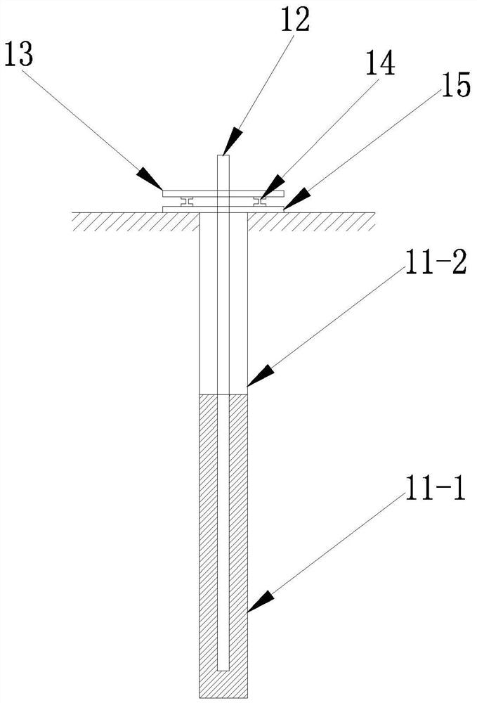
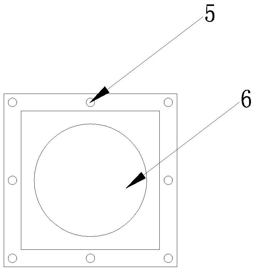
[0026] Example: such as Figure 1-4 As shown, the present invention discloses an anchor combination anti-floating system, including: several main anti-floating anchor assemblies 1, channel steel purlins 2, anchor holes 3 of auxiliary anchoring components and supporting purlins 4; wherein, the main anti-floating anchor The component 1 includes a drill hole 11, a bolt body 12, a polygonal backing plate 13, an I-shaped spacer 14 and a conventional backing plate 15; the I-shaped spacer 14 mainly includes a bolt through hole 5 and an anchor hole 6; the polygonal spacer An anchor hole 6 is formed in the middle of the plate 13 and the conventional backing plate 15, the anchor body 12 is penetrated in the anchor hole 6, and several I-shaped pads 14 are assembled between the polygonal backing plate 13 and the conventional backing plate 15; Yes, the borehole 11 includes an anchoring section 11-1 and a free section 11-2; the anchoring section 11-1 is used to fasten the anchor body 12; th...


PUM


Abstract

The invention relates to an anchor rod combined anti-floating system. The anchor rod combined anti-floating system comprises a plurality of main anti-floating anchor rod assemblies, and the adjacent main anti-floating anchor rod assemblies are connected through channel steel purlines; and each main anti-floating anchor rod assembly comprises a drill hole, an anchor rod body, a polygonal base plate, a conventional base plate and a plurality of I-shaped cushion blocks, wherein an anchor rod hole is formed in the middle of the polygonal base plate and the middle of the conventional base plate, the anchor rod body is arranged in the anchor rod hole in a penetrating mode, and the I-shaped cushion blocks are assembled between the polygonal base plate and the conventional base plate. The anchor rod combined anti-floating system is simple in structure and ingenious in design, has the characteristics of being low in construction cost, good in structural reliability, high in adaptability and the like, and has good construction convenience.

Description

technical field [0001] The invention belongs to the technical field of foundation engineering of geotechnical engineering, and in particular relates to a combination anti-floating system of bolts. Background technique [0002] Anti-floating anchor is a kind of anti-floating measures for underground structures in construction projects. It refers to the structural components set up to resist the structural bottom plate and upper buildings due to the upward displacement of the groundwater level. It is related to the level and change of the groundwater level. [0003] With the rapid development of urban construction, a large number of high-rise buildings, underground garages, sunken squares, subways, underground shopping malls and other buildings have put forward higher requirements for the utilization of underground space. However, in coastal cities such as Hangzhou and Shanghai, where the water-rich underground soil layer is soft soil with a large thickness, accidents caused b...

Claims


Application Information

Patent Timeline
Patent Type & Authority Applications(China)
IPC IPC(8): E02D31/12E02D5/76
CPCE02D31/12E02D5/76
Inventor 王哲刘翰辰许四法崔涵晟杨芸峰
Owner ZHEJIANG UNIV OF TECH
Learn More