
A kind of rotary knuckle device for railway vehicle coupler

A technology for railway vehicles and swivel hooks, which is applied in the direction of railway vehicle coupling accessories, railway car body parts, railway couplings, etc., and can solve the problems of railway vehicle maintenance operations, safety of maintenance personnel from being injured, time-consuming and labor-intensive problems, etc. Achieve the effect of eliminating hidden dangers of accidents, reducing labor intensity and ensuring safety

Active Publication Date: 2022-03-15
崔雲皓
View PDF0 Cites 0 Cited by
  • Summary
  • Abstract
  • Description
  • Claims
  • Application Information

AI Technical Summary

Problems solved by technology

[0002] Each carriage of the railway vehicle is connected by a connecting piece composed of a knuckle head, a knuckle tongue and a knuckle pin. The hook cavity and the hook cavity are equipped with hook lock iron, knuckle push iron and other components. When performing maintenance operations on the hook lock iron, knuckle push iron and other components, due to environmental factors, only the knuckle pin can be taken out. Take out the knuckle weighing about 35kg from the hook head and land it on the ground, and then take out the hook lock iron, knuckle push iron and other accessories for maintenance and replacement. This operation is time-consuming and laborious, and there is a safety hazard for the maintenance personnel to be injured by the knuckle , which brings certain troubles to the maintenance operation of railway vehicles

Method used


Image

  • A kind of rotary knuckle device for railway vehicle coupler
  • A kind of rotary knuckle device for railway vehicle coupler
  • A kind of rotary knuckle device for railway vehicle coupler

Examples


Embodiment Construction

[0022] The following will clearly and completely describe the technical solutions in the embodiments of the present invention with reference to the accompanying drawings in the embodiments of the present invention. Obviously, the described embodiments are only some, not all, embodiments of the present invention. Based on the embodiments of the present invention, all other embodiments obtained by persons of ordinary skill in the art without creative work, any modifications, equivalent replacements, improvements, etc., shall be included in the protection scope of the present invention Inside.

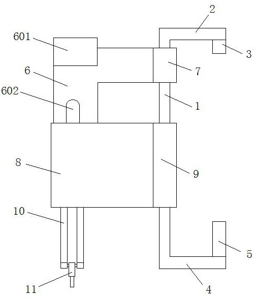
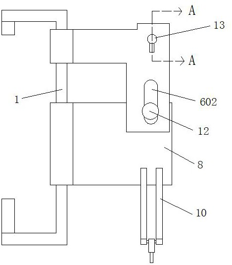
[0023] like Figure 1 to Figure 8 As shown, this embodiment discloses a rotary knuckle device for hanging on the coupler head of a railway vehicle, which includes a positioning piece, an upper clamping iron, and a lower clamping iron. Both the upper clamping iron and the lower clamping iron are rotatably connected to the positioning member. Sliding connection with the lower card iron;

...


PUM


Abstract

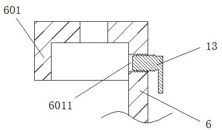
The invention discloses a rotary knuckle device for hanging on the hook head of a railway vehicle, which comprises a positioning piece, an upper clamping iron, and a lower clamping iron. Sliding connection; the positioning member includes a sliding rod, an upper fixing rod, and a lower fixing rod. The upper rotating shaft is coaxially arranged; the upper clamping iron includes an upper clamping plate, one end of the upper clamping plate is rotatably connected with the slide bar and the upper clamping plate can slide along the length direction of the slide bar; the front side of the top of the upper clamping plate is provided with a mounting sleeve , the mounting sleeve is provided with a locking mechanism; the lower clamping iron includes a lower clamping plate, the lower clamping plate is slidably connected to the upper clamping plate, one end of the lower clamping plate is rotatably connected to the slide bar, and the bottom end of the lower clamping plate is fixedly connected with The supporting piece is located under the mounting sleeve and is vertically arranged with the lower clamping plate.

Description

technical field [0001] The invention relates to the field of railway vehicle maintenance, in particular to a rotary knuckle device for hanging a railway vehicle coupler head. Background technique [0002] Each carriage of the railway vehicle is connected by a connecting piece composed of a coupler head, a knuckle tongue and a knuckle pin. The hook cavity and the hook cavity are equipped with hook lock iron, knuckle push iron and other components. When performing maintenance operations on the hook lock iron, knuckle push iron and other components, due to environmental factors, only the knuckle pin can be taken out. Take out the knuckle weighing about 35kg from the hook head and land it on the ground, and then take out the hook lock iron, knuckle push iron and other accessories for maintenance and replacement. , Bring certain troubles to the maintenance operation of railway vehicles. Contents of the invention [0003] The object of the present invention is to solve the abo...

Claims


Application Information

Patent Timeline
Patent Type & Authority Patents(China)
IPC IPC(8): B61G7/00
CPCB61G7/00
Inventor 崔雲皓崔洪军
Owner 崔雲皓
Learn More