Torque module
A module and moment technology, applied in the field of moment modules, can solve the problems of inseparability, high cost, and large volume
- Summary
- Abstract
- Description
- Claims
- Application Information
AI Technical Summary
Problems solved by technology
Method used
Image
Examples
Embodiment 1
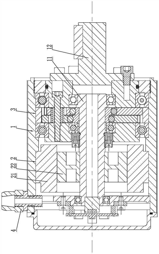
[0028] Such as figure 1 As shown, the torque module includes a housing 1. The housing 1 is used as the installation carrier of the torque module. It is formed by fastening a main housing and a side end cover. The space can be screwed or screwed; the housing 1 can be rectangular or cylindrical.
[0029] In this embodiment, a motor assembly 2 is installed in the housing 1, the output end of the motor assembly 2 is fixed with a motor output shaft 11, the motor assembly 2 is a frameless torque motor, and the motor assembly 2 includes The stator 21 and the rotor 22 cooperate with each other, the outer periphery of the stator 21 of the motor assembly 2 is fixed in the housing 1 with an interference fit, and the inner periphery of the rotor 22 of the motor assembly 2 is fixed in the motor output shaft with an interference fit 11; a reducer assembly 3 is installed on one side of the motor output shaft 11, and an output shaft 12 is fixed at the output end of the reducer assembly 3.
...
Embodiment 2
[0050]The difference between the second embodiment and other embodiments is that the structure of the bearing eccentric sleeve is different, and other structures are the same.
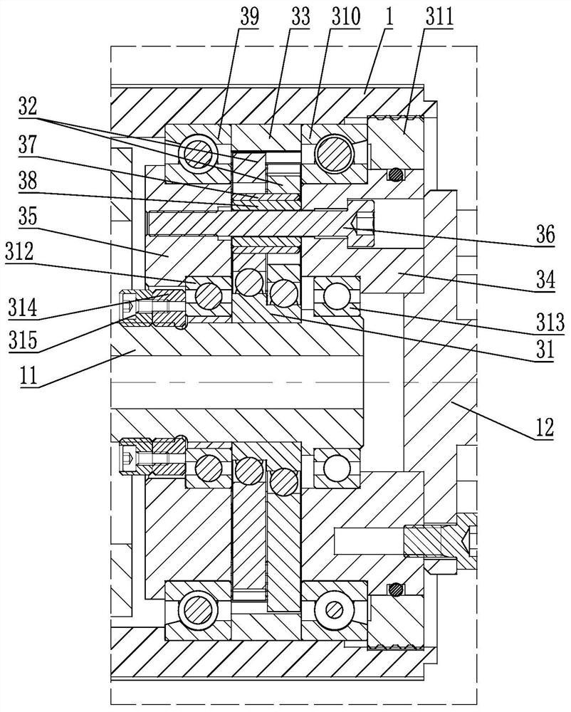
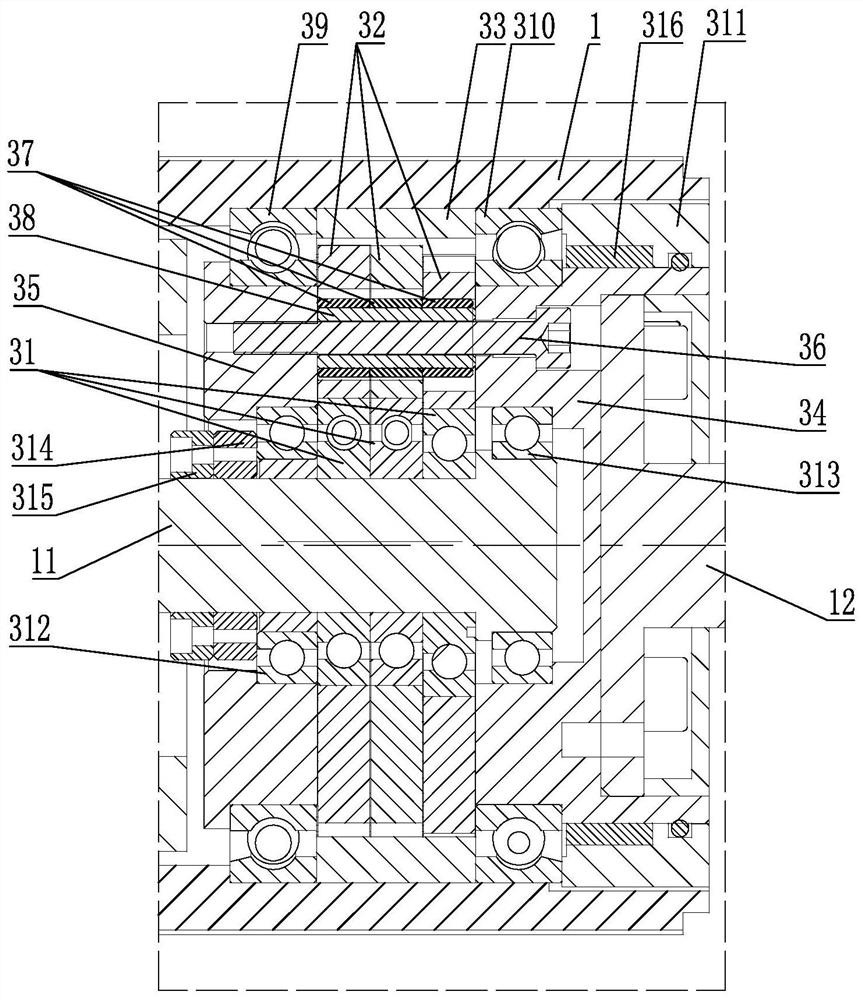
[0051] The bearing eccentric sleeve in Embodiment 1 has an integral structure, see figure 2 , that is, the outer circumference of a bearing eccentric sleeve is equipped with two transmission gears through two bearing balls, and in this embodiment, the bearing eccentric sleeve includes N eccentric bearings sequentially installed on the power output and output shaft, N≥ 2. The phase angle between adjacent eccentric bearings is 360° / N, and an eccentric installation position is formed on the outer circumference of each eccentric bearing, see image 3 The intermediate reducer assembly is provided with three eccentric bearings, the phase angle between the three eccentric bearings is 120°, and each eccentric bearing is equipped with a transmission gear, that is, the number of transmission gears corresponds t...
Embodiment 3
[0053] The difference between the third embodiment and other embodiments is that the structure of the pin sleeve 37 is different, and the other structures are the same.
[0054] The pin bushing in Embodiment 1 has an integrally formed structure, see figure 2 , because the phase angles of the two transmission gears are different, that is, the direction of the force acting on the pin sleeve when the two transmission gears move is different, so that there is a tangential torque in the pin sleeve, and this torque causes the transmission gear and the pin shaft to The friction between the sleeves is relatively large, which will reduce the efficiency of torque transmission. In order to solve this problem, the pin sleeve is set as a segmented structure, see image 3 , in this embodiment, the pin sleeve includes at least two sub-sleeves that are sequentially connected, the number of the sub-sleeves corresponds to the number of the transmission gears, and the outer circumference of eac...
PUM
 Abstract
Description
Claims
Application Information
 - Generate Ideas
- Intellectual Property
- Life Sciences
- Materials
- Tech Scout
- Unparalleled Data Quality
- Higher Quality Content
- 60% Fewer Hallucinations
Browse by: Latest US Patents, China's latest patents, Technical Efficacy Thesaurus, Application Domain, Technology Topic, Popular Technical Reports.
© 2025 PatSnap. All rights reserved.Legal|Privacy policy|Modern Slavery Act Transparency Statement|Sitemap|About US| Contact US: help@patsnap.com


