
Double-end numerical control lathe

A double-head CNC lathe and lathe technology, applied in turning equipment, maintenance and safety accessories, auxiliary devices, etc., can solve the problems of inconvenient collection of oil-based coolant for reuse, increase user labor, and reduce device use efficiency, etc. Achieve the effect of reducing the probability of slippage, reducing labor, and improving stability

Pending Publication Date: 2021-06-08
陈建
View PDF6 Cites 2 Cited by
  • Summary
  • Abstract
  • Description
  • Claims
  • Application Information

AI Technical Summary

Problems solved by technology

[0003] In the process of realizing the present invention, it is found that at least the following problems in the prior art have not been resolved: 1. After the double-headed CNC lathe cuts the workpiece, a large amount of iron waste chips fall, which is not convenient for the user to pull out the iron waste chips The iron waste is processed by the box, which improves the labor force of the user;
[0004] 2. In the process of collecting iron waste, iron waste often contains a large amount of oil-based coolant, but when users clean up iron waste, they often directly use the coolant attached to the iron waste Collected together with iron waste, it is not convenient for users to collect oil-based coolant for reuse, reducing the use efficiency of the device

Method used


Image

  • Double-end numerical control lathe
  • Double-end numerical control lathe
  • Double-end numerical control lathe

Examples


Embodiment Construction

[0032] The technical solutions of the present invention will be clearly and completely described below in conjunction with the embodiments. Obviously, the described embodiments are part of the embodiments of the present invention, but not all of them. Based on the embodiments of the present invention, all other embodiments obtained by persons of ordinary skill in the art without making creative efforts belong to the protection scope of the present invention.

[0033]In describing the present invention, it is to be understood that the terms "center", "longitudinal", "transverse", "length", "width", "thickness", "upper", "lower", "front", " Back", "Left", "Right", "Vertical", "Horizontal", "Top", "Bottom", "Inner", "Outer", "Clockwise", "Counterclockwise", etc. or The positional relationship is based on the orientation or positional relationship shown in the drawings, which is only for the convenience of describing the present invention and simplifying the description, rather th...


PUM


Abstract

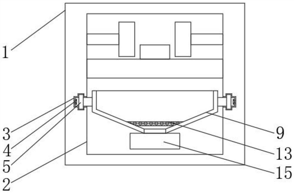
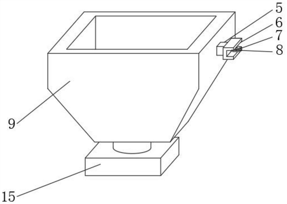
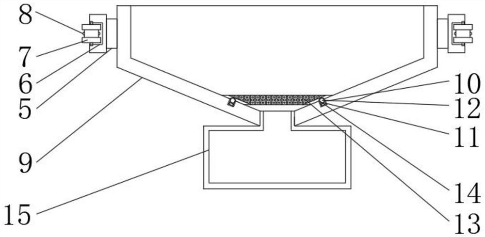
The invention provides a double-end numerical control lathe which comprises a lathe body, a collecting groove is formed in the lathe body, a sliding groove is formed in the outer surface of one side of the collecting groove, a clamping block is slidably connected to the interior of the sliding groove, a collecting hopper is fixedly connected to the outer surface of the other side of the clamping block, and a filter screen is arranged on the inner surface of the collecting hopper. The outer surface of the lower end of the collecting hopper is in threaded connection with a material collecting box, a rectangular groove is formed in the outer surface of one side of the clamping block, a rolling wheel is arranged in the rectangular groove and is of an I-shaped structure, a protruding block is fixedly connected to the concave position of the rolling wheel, a clamping groove is formed in the sliding groove, and the clamping groove and the protruding block are mutually clamped. According to the double-end numerical control lathe, a user can conveniently pull out the collecting hopper, waste chips in the collecting hopper are treated in a centralized mode, meanwhile, oil-based cooling liquid attached to the waste chips can be recycled, and therefore the using efficiency of the double-end numerical control lathe is improved, and the production cost of a user is reduced.

Description

technical field [0001] The invention relates to the technical field of a double-head numerical control lathe, in particular to a double-head numerical control lathe. Background technique [0002] Double-head CNC lathe is a double-head lathe operated by a modern CNC computer system. Compared with ordinary double-head lathes, the processing has the characteristics of more refinement and automation. There is a turning point at each end, and a CNC system is used for processing. control. [0003] In the process of realizing the present invention, it is found that at least the following problems in the prior art have not been resolved: 1. After the double-headed CNC lathe cuts the workpiece, a large amount of iron waste chips fall, which is not convenient for the user to pull out the iron waste chips The iron waste is processed by the box, which improves the labor force of the user; [0004] 2. In the process of collecting iron waste, iron waste often contains a large amount of ...

Claims


Application Information

Patent Timeline
IPC IPC(8): B23B25/00B23Q11/10
CPCB23B25/00B23Q11/10B23Q11/1069
Inventor 陈建鲍合祥朱齐福
Owner 陈建
Learn More