Automatic gas-liquid separation method
An automatic separation, gas-liquid technology, applied in separation methods, dispersed particle separation, chemical instruments and methods, etc., can solve problems such as unsuitable for explosion-proof and toxic and harmful production sites, poor applicability, and inability to realize automatic separation.
- Summary
- Abstract
- Description
- Claims
- Application Information
AI Technical Summary
Problems solved by technology
Method used
Image

Examples
Embodiment 1
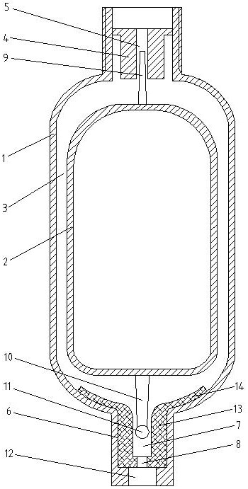
[0034] see figure 1 , a gas-liquid automatic separation method, comprising the following steps:
[0035] S1. Pass the pressurized liquid-containing sample gas through the upper positioning pin bracket 4 into the interlayer 3 between the outer cylinder 1 and the stainless steel buoy 2, the liquid phase flows downward under the action of gravity, and the gas phase rises and is discharged through the upper positioning pin bracket 4;
[0036] S2. When the liquid phase flows into the bottom space between the bottom of the outer cylinder 1 and the bottom of the stainless steel buoy 2, the buoyancy generated by the liquid relative to the stainless steel buoy 2 is greater than the sample gas pressure and the gravity of the stainless steel buoy 2, the stainless steel buoy 2 and the lower positioning pin The spherical plug 11 on 10 floats up, and the liquid phase is discharged from the liquid outlet 12 at the bottom of the outer cylinder 1 through the circular through hole 8;
[0037] ...
Embodiment 2
[0041] see figure 1 , a gas-liquid automatic separation method, comprising the following steps:
[0042] S1. Pass the pressurized liquid-containing sample gas through the upper positioning pin bracket 4 into the interlayer 3 between the outer cylinder 1 and the stainless steel buoy 2, the liquid phase flows downward under the action of gravity, and the gas phase rises and is discharged through the upper positioning pin bracket 4;
[0043] S2. When the liquid phase flows into the bottom space between the bottom of the outer cylinder 1 and the bottom of the stainless steel buoy 2, the buoyancy generated by the liquid relative to the stainless steel buoy 2 is greater than the sample gas pressure and the gravity of the stainless steel buoy 2, the stainless steel buoy 2 and the lower positioning pin The spherical plug 11 on 10 floats up, and the liquid phase is discharged from the liquid outlet 12 at the bottom of the outer cylinder 1 through the circular through hole 8;
[0044] ...
Embodiment 3
[0049] see figure 1 , a gas-liquid automatic separation method, comprising the following steps:
[0050] S1. Pass the pressurized liquid-containing sample gas through the upper positioning pin bracket 4 into the interlayer 3 between the outer cylinder 1 and the stainless steel buoy 2, the liquid phase flows downward under the action of gravity, and the gas phase rises and is discharged through the upper positioning pin bracket 4;
[0051] S2. When the liquid phase flows into the bottom space between the bottom of the outer cylinder 1 and the bottom of the stainless steel buoy 2, the buoyancy generated by the liquid relative to the stainless steel buoy 2 is greater than the sample gas pressure and the gravity of the stainless steel buoy 2, the stainless steel buoy 2 and the lower positioning pin The spherical plug 11 on 10 floats up, and the liquid phase is discharged from the liquid outlet 12 at the bottom of the outer cylinder 1 through the circular through hole 8;
[0052] ...
PUM
 Abstract
Description
Claims
Application Information
 - R&D
- Intellectual Property
- Life Sciences
- Materials
- Tech Scout
- Unparalleled Data Quality
- Higher Quality Content
- 60% Fewer Hallucinations
Browse by: Latest US Patents, China's latest patents, Technical Efficacy Thesaurus, Application Domain, Technology Topic, Popular Technical Reports.
© 2025 PatSnap. All rights reserved.Legal|Privacy policy|Modern Slavery Act Transparency Statement|Sitemap|About US| Contact US: help@patsnap.com