Medicine smearing device for endocrine nursing
A technology of endocrine and medicine, applied in the direction of medicine equipment, medicine equipment, physical therapy, etc., can solve the problems of no massage effect, short application time, unfavorable ointment absorption, etc., to achieve simple and convenient application, good absorption effect, Ease of use
- Summary
- Abstract
- Description
- Claims
- Application Information
AI Technical Summary
Problems solved by technology
Method used
Image
Examples
Embodiment 1
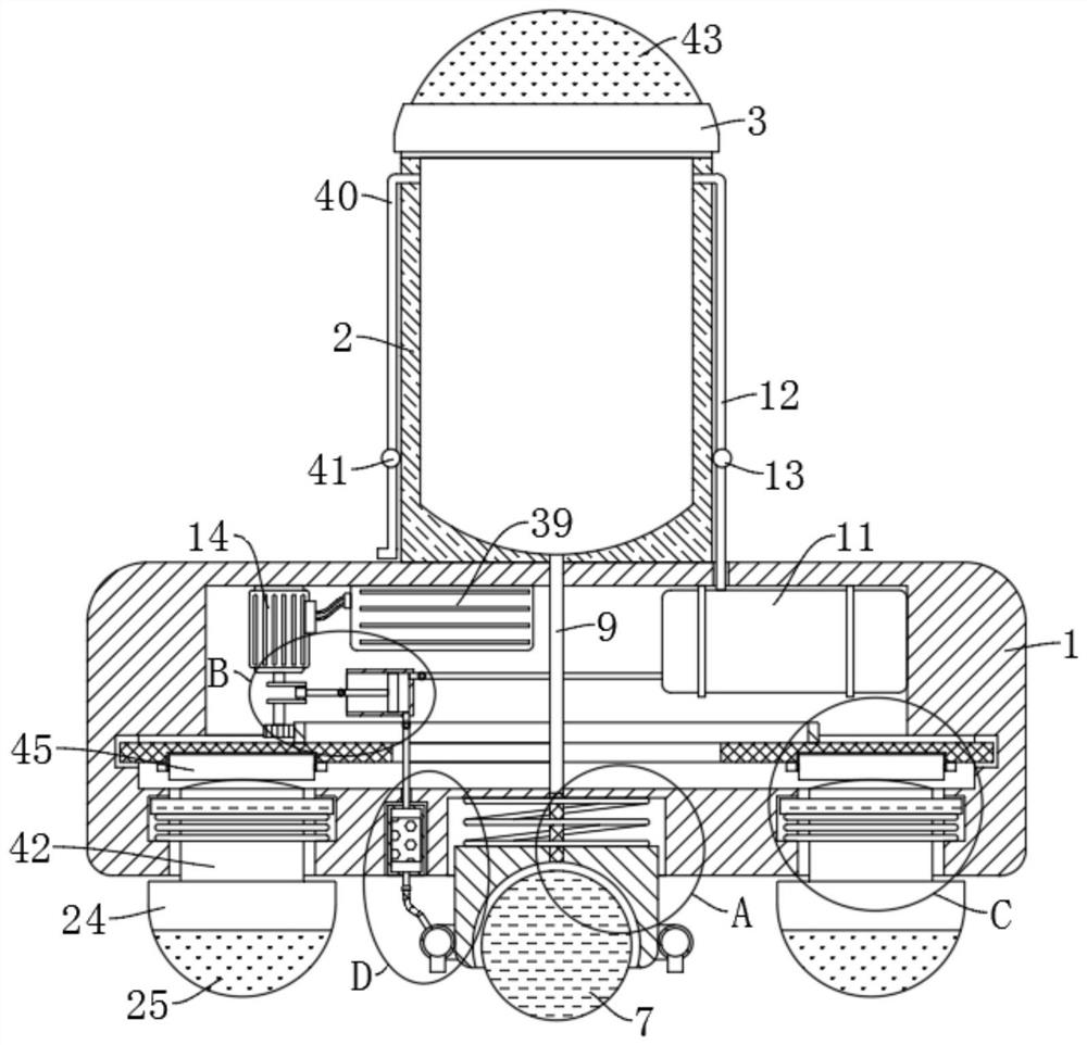
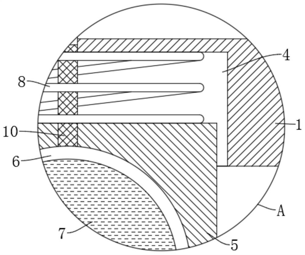
[0030] refer to Figure 1-5 , a drug application device for endocrine care, comprising a device box 1, the upper end of the device box 1 is fixedly installed with a storage tank 2, the upper end of the storage tank 2 is threadedly connected with a cover plate 3, and the bottom of the device box 1 is provided with a sliding cavity 4, The sliding chamber 4 is slidably connected with a top tight slider 5, which is elastically connected with the inner top of the slide chamber 4 by a top tight spring 8, and the lower end of the top tight slider 5 is provided with a groove 6, and the groove 6 is provided with a smear ball 7 which is slidably connected to it. The inner bottom of the storage tank 2 is provided with a conveying pipe 9 extending into the sliding chamber 4. The end of the conveying pipe 9 is fixedly connected with a first A hose 10, an air storage tank 11 is fixedly installed in the device box 1, the output end of the air storage tank 11 is fixedly connected with an air ...
Embodiment 2
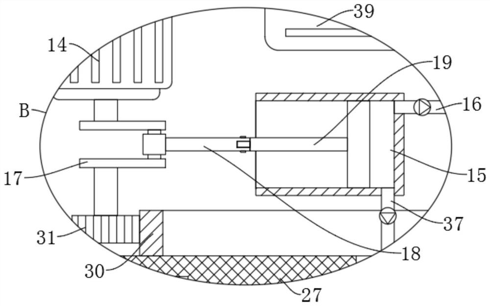
[0034] refer to figure 1 and image 3, is basically the same as Embodiment 1, furthermore: the inflation mechanism includes a motor 14 fixedly installed inside the device box 1, the output end of the motor 14 is fixedly connected with a crankshaft 17, and an inflator 15 is fixedly installed in the device box 1, and the crankshaft 17 is rotatably connected with a connecting rod 18, and the end of the connecting rod 18 is rotatably connected to the end of the push rod 19 of the pump 15, and the output end of the pump 15 is fixedly connected with an inflatable tube 16, and the end of the inflatable tube 16 is connected to the end of the gas storage tank 11. The input end is fixedly connected and communicated, the motor 14 will drive the crankshaft 17 to rotate, the crankshaft 17 will drive the push rod 19 to slide left and right through the connecting rod 18 based on the principle of the crank slider, and the push rod 19 will make the pump 15 pass through the inflatable tube 16 p...
Embodiment 3
[0037] refer to figure 1 , image 3 and Figure 4 , is basically the same as Embodiment 1, furthermore: the massage mechanism includes a plurality of slideways 20 arranged at the lower end of the device box 1 and distributed circumferentially, and slide bars 42 are all slidably connected in the plurality of slideways 20, and the plurality of slide bars The lower end of 42 is all fixedly installed with massage head 24, and the outer wall of a plurality of slide bars 42 is all fixedly connected with annular plate 22, is provided with the chute 21 that cooperates with annular plate 22 in the slideway 20, the ring plate 22 and chute 21 The lower ends are elastically connected by a return spring 23, and the inner bottom of the device box 1 is rotatably connected with an annular disk 27 through a device chamber 26, and the lower end of the annular disk 27 is fixedly connected with a plurality of circumferentially distributed upper bumps 28, and a plurality of sliding rods 42. The ...
PUM
 Abstract
Description
Claims
Application Information
 - R&D
- Intellectual Property
- Life Sciences
- Materials
- Tech Scout
- Unparalleled Data Quality
- Higher Quality Content
- 60% Fewer Hallucinations
Browse by: Latest US Patents, China's latest patents, Technical Efficacy Thesaurus, Application Domain, Technology Topic, Popular Technical Reports.
© 2025 PatSnap. All rights reserved.Legal|Privacy policy|Modern Slavery Act Transparency Statement|Sitemap|About US| Contact US: help@patsnap.com


