
Zea mays L. harvester

A corn harvester and corn stalk technology, which is applied to harvesters, agricultural machinery and implements, threshing equipment, etc., can solve the problems of affecting the efficiency of impurity removal, low impurity removal efficiency, and low transmission efficiency.

Active Publication Date: 2021-06-08
常州常发重工科技有限公司
View PDF7 Cites 1 Cited by
  • Summary
  • Abstract
  • Description
  • Claims
  • Application Information

AI Technical Summary

Problems solved by technology

In this process of waste removal, when there are too many impurities, it is easy to cause blockage and affect the efficiency of waste removal; in addition, during the process of waste removal, some impurities will fall into the peeling machine together with the ears, resulting in too many impurities in the ear collection box, and the removal of waste less effective
[0003] At present, there is an air-suction wind-powered trash removal device on the market, which is usually fixed on the side of the ear elevator. The wind generated by the trash removal fan sucks straw debris and other impurities into the chopping device, and then discharges them through the fan channel. However, At present, there are still various problems in the design of the transmission system of the air-suction exhaust fan, which leads to problems such as the transmission system is easily damaged, the transmission efficiency is low, and the efficiency of the exhaust is not high.

Method used


Image

  • Zea mays L. harvester
  • Zea mays L. harvester
  • Zea mays L. harvester

Examples


Embodiment Construction

[0052] In order to more clearly illustrate the technical solutions in the embodiments of the present invention or the prior art, the following will briefly introduce the drawings that need to be used in the description of the embodiments or the prior art. Obviously, the accompanying drawings in the following description are only These are some embodiments of the present invention. Those skilled in the art can also obtain other drawings based on these drawings without creative work.

[0053] In order to make the drawing concise, each drawing only schematically shows the parts related to the present invention, and they do not represent the actual structure of the product. In addition, to make the drawings concise and easy to understand, in some drawings, only one of the components having the same structure or function is schematically shown, or only one of them is marked. Herein, "a" not only means "only one", but also means "more than one".

[0054] It should also be further u...


PUM


Abstract

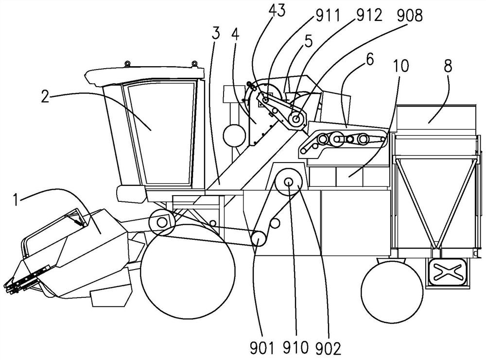
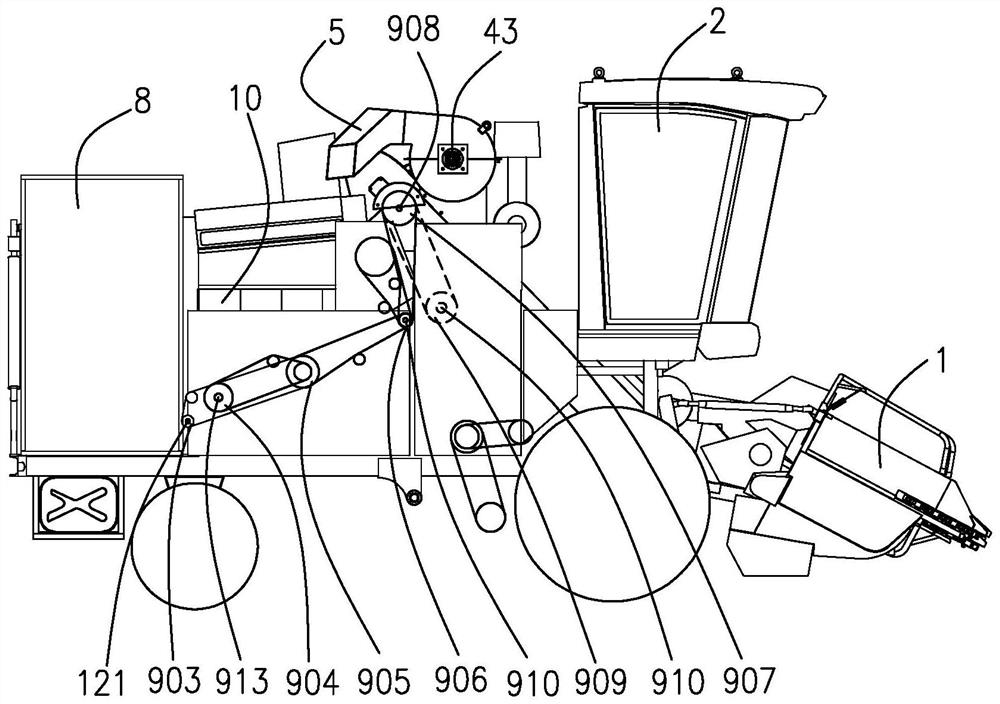
The invention provides a Zea mays L. harvester, The invention provides a Zea mays L. harvester, which comprises a first impurity discharging fan part, a first installation shaft, a vibrating sieve, an eccentric chain wheel shaft, a second impurity discharging fan part and a second installation shaft, wherein the first installation shaft is cooperated with the first impurity discharging fan part to drive the first impurity discharging fan part; the vibrating sieve is used for carrying out vibration cleaning on fallen Zea mays L. kernels; the eccentric chain wheel shaft drives the vibrating sieve to carry out reciprocating motion; the second impurity discharging fan part is arranged on the tail part of the vibrating sieve for blowing out stems and bracteal leaves which fall from the vibrating sieve and is used for realizing further cleaning of the Zea mays L. kernels; the second installation shaft is cooperatively connected with the second impurity discharging fan part to drive the second impurity discharging fan part to rotate; the first impurity discharging fan part comprises a first impurity discharging fan; the second impurity discharging fan part comprises a second impurity discharging fan; the eccentric chain wheel shaft is arranged between the first installation shaft and the second installation shaft; the first installation shaft, the second installation shaft and the eccentric chain wheel shaft are arranged in parallel; and the axial line of the eccentric chain wheel shaft is not positioned in a plane formed by the axial line of the first installation shaft and the axial line of the second installation shaft.

Description

technical field [0001] The invention relates to the technical field of engines, and in particular provides a corn harvester with a double blower blower system. Background technique [0002] When the corn harvester is harvesting corn, the corn stalks, leaves and weeds can easily enter the working mechanism of the harvester and the ear collection box, resulting in low purity of the harvested corn ears. In severe cases, the working mechanism will be blocked and machine failure will occur. At present, the wind-powered miscellaneous removal device of the corn harvester sold on the market is usually fixed below the ear elevator, and the wind force produced by the miscellaneous fan blows the airflow along the oblique direction of the ear elevator through the air duct. After the ears of corn are transported to the upper end of the elevator, they fall into the peeling machine, and impurities such as straw residues are blown upwards obliquely with the wind force, and are removed to th...

Claims


Application Information

Patent Timeline
Patent Type & Authority Applications(China)
IPC IPC(8): A01D45/02A01F11/06A01F12/40A01F12/44
CPCA01D45/021A01F11/06A01F12/44A01F12/40Y02P60/14
Inventor 杨亚帆李小坡王浩陈燕燕张军朋崔俊杰梁耀飞
Owner 常州常发重工科技有限公司
Learn More