Medical waste treatment equipment with cleaning function

A technology for medical waste and treatment equipment, which is applied in the direction of blower equipment, combustion equipment, lighting and heating equipment, etc., which can solve the problems of poor exhaust gas exhaust, low practicability, and inconvenient operation, so as to reduce the occupation of space, The effect of reducing cost input and reducing the number of placements

Inactive Publication Date: 2021-06-04
邵欠欠
View PDF0 Cites 4 Cited by
  • Summary
  • Abstract
  • Description
  • Claims
  • Application Information

AI Technical Summary

Problems solved by technology

[0003] At present, the medical waste on the market needs to be manually cleaned inside the equipment after incineration, which will increase the labor intensity of the workers, is inconvenient to operate, and has low practicability. However, most incineration equipment directly incinerates waste, which will lead to waste incineration. Incomplete, and transmission processing equipment, due to insufficient oxygen supply or insufficient contact between oxygen and garbage during the combustion process, will also lead to incomplete combustion of garbage. In addition, when traditional garbage treatment equipment burns garbage, the exhaust gas Direct discharge into the atmosphere will cause serious pollution to the atmosphere. There will also be a lot of metal and non-metallic substances in the combustion residue. It is necessary to manually sort the metals in the residue. When the workers clean up, there may be workers and workers. There is no contact with the incinerated garbage, and then the infection of germs occurs. In addition, each component of the existing garbage disposal equipment needs to be equipped with a separate drive mechanism, which increases the cost of the enterprise and occupies space, and the exhaust gas sometimes occurs during the discharge process. The phenomenon of poor exhaust, so a medical waste disposal equipment with cleaning function is proposed to solve the above-mentioned problems

Method used


Image

  • Medical waste treatment equipment with cleaning function
  • Medical waste treatment equipment with cleaning function
  • Medical waste treatment equipment with cleaning function

Examples


Embodiment Construction

[0035] The following will clearly and completely describe the technical solutions in the embodiments of the present invention with reference to the accompanying drawings in the embodiments of the present invention. Obviously, the described embodiments are only some, not all, embodiments of the present invention. Based on the embodiments of the present invention, all other embodiments obtained by persons of ordinary skill in the art without making creative efforts belong to the protection scope of the present invention.

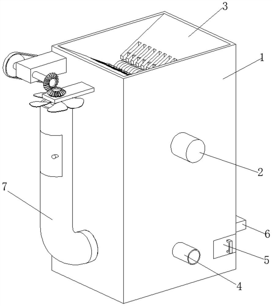
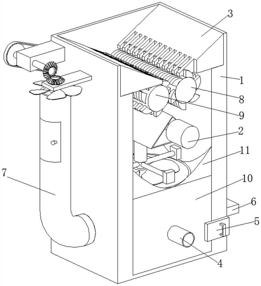
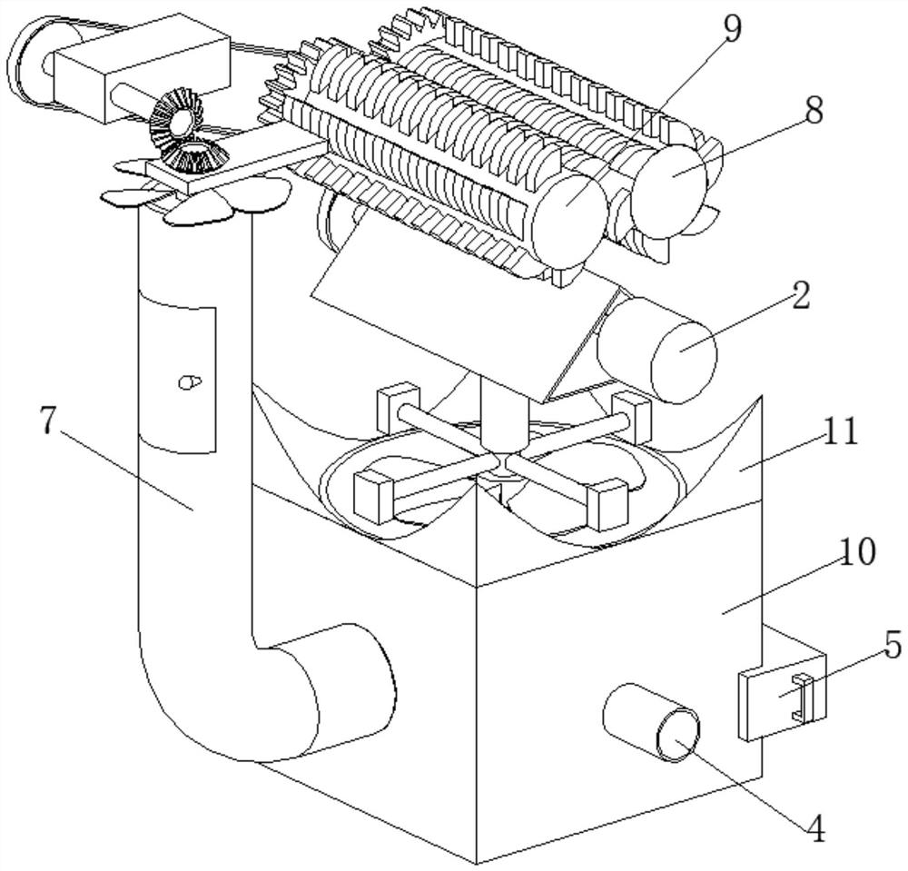
[0036] A medical waste treatment equipment with cleaning function, such as Figure 1-Figure 6As shown, the box body 1 is included, the right side of the box body 1 is provided with a transmission mechanism 2, the inner wall of the box body 1 is welded with two slider blocks 3, and the right side of the box body 1 is connected with a feed pipe 4, and the feeding The pipe 4 is located below the transmission mechanism 2, the inner wall of the rear part of the box...


PUM


Abstract

The invention relates to the technical field of waste treatment, and discloses medical waste treatment equipment with a cleaning function. The equipment comprises a box body, wherein a transmission mechanism is arranged on the right side of the box body, two sliding blocks are welded on the inner wall of the box body, the right side of the box body communicates with a feeding pipe, the feeding pipe is positioned below the transmission mechanism, a sliding block is slidably connected to the inner wall of the rear portion of the box body, an electromagnet is fixedly installed on the rear portion of the box body, a purification mechanism is arranged on the front portion of the box body, a first smashing roller and a second smashing roller are rotatably connected to the inner wall of the box body, a treatment box is fixedly installed on the bottom wall inside the box body, and an inclined block is welded to the top of the treatment box. According to the equipment, cleaning liquid is injected into the feeding pipe, and then the inner wall of the treatment box can be automatically cleaned through the transmission mechanism, so that manual cleaning by workers is not needed, the risk of contact infection is reduced, and the working efficiency is further improved.

Description

technical field [0001] The invention relates to the technical field of garbage disposal, in particular to medical garbage disposal equipment with a cleaning function. Background technique [0002] Garbage is solid waste generated in human daily life and production. Due to the large amount of discharge, complex and diverse components, and polluting, resourceful and social nature, it needs harmless, resourceful, reduction and socialized treatment. If it is not handled properly, it will pollute the environment, affect environmental sanitation, waste resources, destroy the safety of production and life, and disrupt social harmony. Garbage disposal is to quickly remove garbage, conduct harmless treatment, and finally make reasonable use of it. Applied waste disposal methods are sanitary landfill, high-temperature composting and incineration, and the purpose of waste disposal is harmlessness, resource utilization and reduction. [0003] At present, the medical waste on the market...

Claims


Application Information

Patent Timeline
Patent Type & Authority Applications(China)
IPC IPC(8): F23G5/033F23G5/12F23G5/44F23L5/02F23J15/02B08B3/10B03C3/00
CPCB03C3/00B08B3/102F23G5/033F23G5/12F23G5/44F23J15/022F23L5/02
Inventor 邵欠欠
Owner 邵欠欠
Why Eureka
Try Eureka