
Intelligent vacuum pump for clinical treatment

A clinical treatment, vacuum pump technology, applied in the direction of pumps, pump control, pump components, etc., can solve the problems of inconvenient portability, poor load-bearing capacity, and inconvenient switching

Pending Publication Date: 2021-06-04
西安国际医学中心有限公司
View PDF7 Cites 0 Cited by
  • Summary
  • Abstract
  • Description
  • Claims
  • Application Information

AI Technical Summary

Problems solved by technology

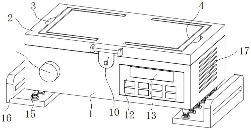
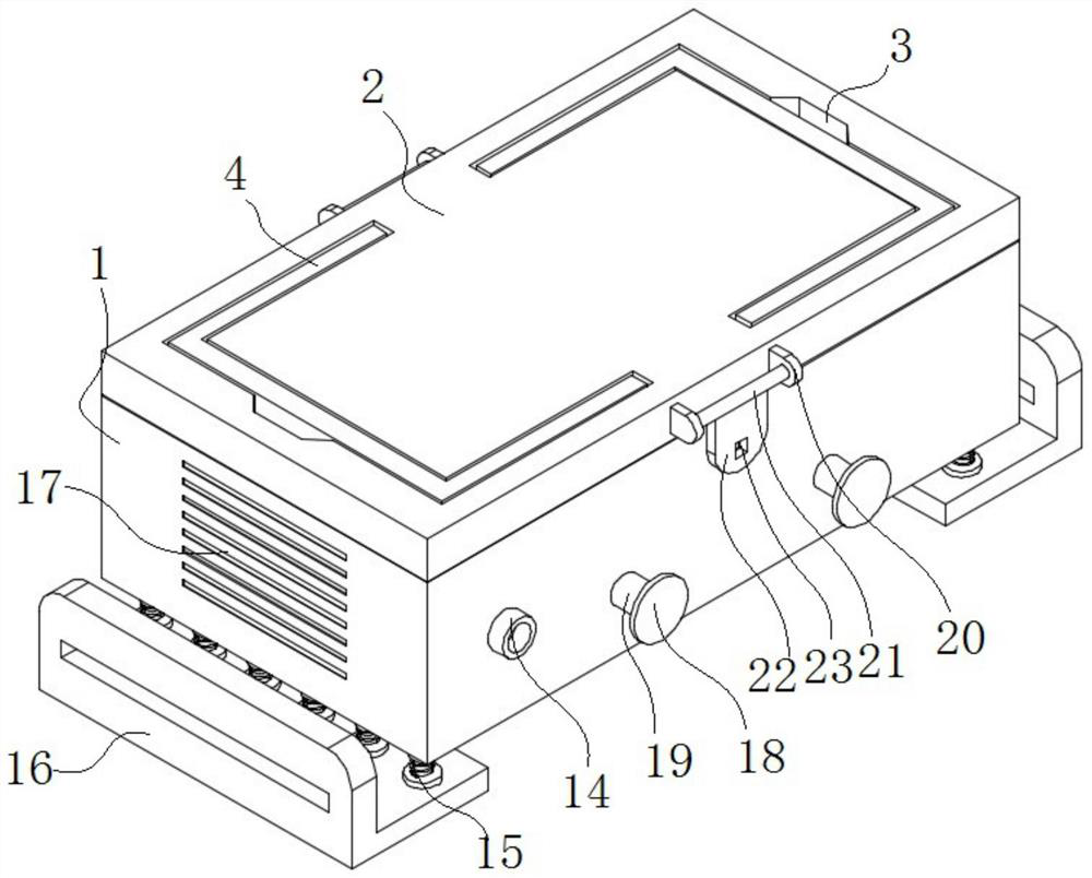
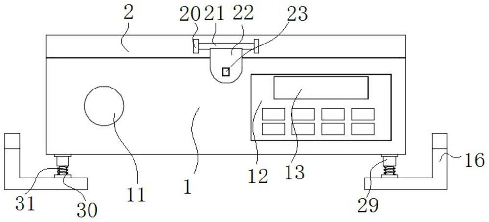
[0004] The purpose of the present invention is to provide an intelligent vacuum pump for clinical treatment, through the voice control module and circuit board structure, it is convenient to open and close the voice control control device, save its operation time, ensure the extraction quality of the vacuum bag, and at the same time facilitate voice control through the clamping device The installation and disassembly of the module is convenient for later maintenance and inspection, and the installation and disassembly of the top cover is facilitated by the buckle device, which is convenient for the inspection and maintenance of the circuit board and the vacuum pump body in the later stage. The handle structure is convenient for carrying the installation box. At the same time, the load-bearing capacity of the installation box is conveniently improved through the structure of the support device and the support plate, and the service life of the installation box is improved, and the hose is conveniently placed through the hose rack, which improves the space utilization of the device and solves the existing inconvenient switch. Problems with inconvenient portability and poor load-bearing capacity

Method used


Image

  • Intelligent vacuum pump for clinical treatment
  • Intelligent vacuum pump for clinical treatment
  • Intelligent vacuum pump for clinical treatment

Examples


Embodiment Construction

[0029] Next, the technical solutions in the embodiments of the present invention will be apparent from the embodiment of the present invention, and it is clearly described, and it is understood that the described embodiments are merely embodiments of the present invention, not all of the embodiments. Based on the embodiments in the present invention, those of ordinary skill in the art will belong to the scope of the present invention in the scope of the present invention without any other embodiments obtained without creative labor.

[0030] In the description of the invention, it is to be understood that the terms "upper", "in", "outside", "within", etc., etc., "within", "" "", "" I suggest that the components or components referred to must have specific orientation, constructed and operated in specific orientation, and thus is not to be construed as limiting the invention.

[0031] See Figure 1-6 As shown, the present invention is a clinical treatment of a smart vacuum pump, inc...


PUM


Abstract

The invention discloses an intelligent vacuum pump for clinical treatment, and relates to the technical field of medical equipment. The intelligent vacuum pump comprises a mounting box body, a top cover, a mounting frame, clamping devices, a sound control module, a circuit board and a vacuum pump body, the mounting box body is of a cavity structure, the top cover is mounted on the upper surface of the mounting box body, the mounting frame is arranged in the mounting box body, the sound control module is mounted in the mounting frame, the clamping devices are mounted on the two opposite surfaces in the mounting frame, the clamping devices are matched with one surface of the sound control module, the circuit board is installed on one side of the mounting frame, and the vacuum pump body is installed on one side of the circuit board. Through the sound control module and the circuit board structure, opening and closing of the sound control device are facilitated, the operation time of the sound control device is saved, the extraction quality of a vacuum bag is guaranteed, the mounting box body is convenient to carry through a handle structure, meanwhile the bearing capacity of the mounting box body is conveniently improved through a supporting device and a supporting plate structure, hoses can be conveniently placed through a hose frame, and the space utilization rate of the device is increased.

Description

Technical field [0001] The present invention belongs to the technical field of medical equipment, and more particularly to a clinical treatment of smart vacuum pump. Background technique [0002] Since the reform and opening up, China's national economy has been rapidly increased, with "scientific and technological innovation, independent innovation" has become the mainstream of domestic industrial development, "technology strong, China strong" has become a process of promoting China's scientific and technological revolution, China's industrial is gradually summarizing Type, energy saving and emission reduction, low carbon, high-tech intelligent direction, the vacuum pump refers to a device or equipment that is vacuum to obtain vacuum by taking the container by mechanical, physics, chemical or physicochemistry, and The vacuum pump is to improve, produce and maintain vacuum in a certain closed space. According to the working principle of the vacuum pump, the vacuum pump can basica...

Claims


Application Information

Patent Timeline
IPC IPC(8): F04B37/14F04B39/12F04B39/14F04B49/06
CPCF04B37/14F04B49/06F04B39/14F04B39/125F04B39/123F04B39/121
Inventor 赵本华温宏囡王海云马军军曹继宗惠斌夏飞飞何积蓉
Owner 西安国际医学中心有限公司
Learn More