
Self-weight pressure maintaining mechanism

A pressure-holding block and pressure head technology, which is applied in the direction of presses and manufacturing tools, can solve problems such as difficulty in ensuring assembly accuracy, deflection of thin plate parts, and damage to workpieces, and achieves a simple structure, improved pressure-holding effect, and convenient use. Effect

Pending Publication Date: 2021-06-04
SUZHOU RS TECH
View PDF0 Cites 3 Cited by
  • Summary
  • Abstract
  • Description
  • Claims
  • Application Information

AI Technical Summary

Problems solved by technology

[0003] First of all, some thin-plate parts are not flat surfaces, and their surfaces are curved, so it is difficult to ensure the accuracy of assembly during the assembly process; because the surface of the workpiece is curved, the contact area of ​​the surface is small during the assembly process, and the deflection of the thin-plate parts often occurs When the situation arises, for this reason, it is necessary to adjust the level of the workpiece first, and then maintain the pressure on the workpiece. In the existing pressure maintaining mechanism, a single set of counterweights is used to press the workpiece by its own weight to adjust the workpiece and maintain pressure;
[0004] However, in the actual pressure-holding process, the gravity required to drive the workpiece deflection when adjusting the workpiece is greater than the gravity required for pressure-holding, and the existing pressure-holding mechanism is not easy to adjust the gravity according to the assembly position of the workpiece , it is difficult to meet the needs of different gravity when the workpiece is adjusted or maintained at the same time. If the counterweight meets the gravity requirements of the adjusted workpiece, at this time, the gravity of the counterweight is easy to damage the workpiece during the pressure maintaining process; and if the counterweight The gravity of the counterweight block meets the gravity required for the pressure maintaining of the workpiece, and the gravity of the counterweight block is difficult to drive the deflection of the workpiece, which leads to the unsatisfactory effect of the existing pressure maintaining mechanism on the pressure maintaining of the thin plate

Method used


Image

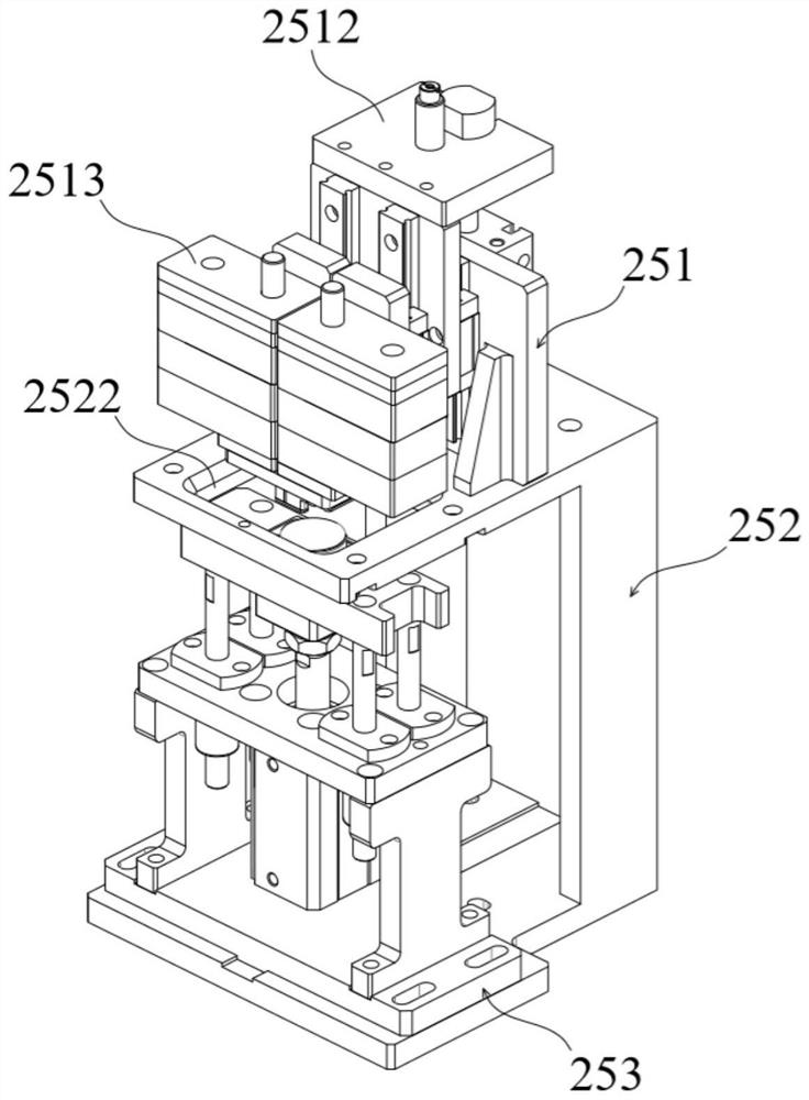
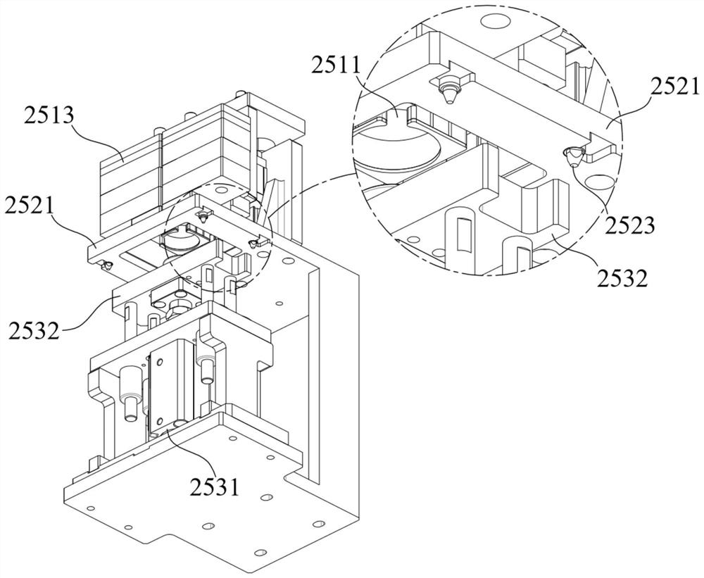
  • Self-weight pressure maintaining mechanism
  • Self-weight pressure maintaining mechanism
  • Self-weight pressure maintaining mechanism

Examples


Embodiment Construction

[0053] The technical solutions in the embodiments of the present invention will be clearly and completely described below in conjunction with the accompanying drawings in the embodiments of the present invention. Obviously, the described embodiments are only part of the embodiments of the present invention, not all of them. Based on the implementation methods in the present invention, all other embodiments obtained by persons of ordinary skill in the art without making creative efforts belong to the protection scope of the present invention.

[0054] In the drawings, the shapes and dimensions may be exaggerated for clarity, and the same reference numerals will be used throughout to designate the same or like parts.

[0055] Unless otherwise defined, the technical terms or scientific terms used herein shall have the usual meanings understood by those skilled in the art to which the present invention belongs. "First", "second" and similar words used in the specification of the p...


PUM


Abstract

The invention relates to a self-weight pressure maintaining mechanism. The self-weight pressure maintaining mechanism comprises a connecting seat and a pressing part; a limiting surface for bearing a workpiece is arranged at the top end of the connecting seat; the pressing part is positioned above the limiting surface, wherein the pressing part comprises a pressure head module and at least two groups of counterweight modules, and the counterweight modules are downwards pressed at the top end of the pressure head module, so that the pressure head module is downwards pressed on the workpiece, and the workpiece is driven to be adjusted from an inclined state to a balanced state. When the workpiece is in the inclined state, the counterweight modules press the pressure head module downwards to enable the pressure head module to press the inclined vertex of the workpiece downwards, and then the workpiece is driven to deflect to be in the balanced state; when the workpiece is in the balanced state, each group of counterweight module acts in a corresponding area where the pressure head module presses the workpiece, the position of the workpiece is adjusted through the self-weight pressure maintaining mechanism, pressure maintaining is carried out on the workpiece, and the mounting precision of the workpiece is guaranteed.

Description

technical field [0001] The invention relates to the field of non-standard automatic assembly, in particular to a self-weight and pressure-maintaining mechanism. Background technique [0002] In the field of non-standard automation, in the assembly process, when no less than two parts are pressed together to form a whole, it is well known to use a pressure maintaining mechanism to maintain pressure on the overall workpiece. The inventor found that the existing pressure maintaining The mechanism has at least the following problems in the process of holding the thin plate parts: [0003] First of all, some thin-plate parts are not flat surfaces, and their surfaces are curved, so it is difficult to ensure the accuracy of assembly during the assembly process; because the surface of the workpiece is curved, the contact area of ​​the surface is small during the assembly process, and the deflection of the thin-plate parts often occurs When the situation arises, for this reason, it ...

Claims


Application Information

Patent Timeline
Patent Type & Authority Applications(China)
IPC IPC(8): B30B9/00B30B15/00
CPCB30B9/00B30B15/00
Inventor 吴华缪磊徐振光袁文卿谢献民周永昌
Owner SUZHOU RS TECH
Learn More