
Sectional material sawing device for building decoration and using method thereof

A technology for architectural decoration and sawing devices, which is applied in the direction of sawing machine devices, metal sawing equipment, metal processing equipment, etc., can solve the problems of high labor intensity, waste of metal profiles, and low work efficiency, and improve work safety Sexuality, reduce labor output, and improve work efficiency

Pending Publication Date: 2021-06-04
向艳清
View PDF1 Cites 1 Cited by
  • Summary
  • Abstract
  • Description
  • Claims
  • Application Information

AI Technical Summary

Problems solved by technology

[0003] The existing patent technology CN209681309U discloses a cutting device for processing aluminum profiles, which includes a moving work plate, a sliding base, a clamp moving assembly, a moving turntable, a rotating card slot, and a saw blade, which can connect clamping and cutting into a whole, And the position of the aluminum profile clamped by the cutting fixture assembly is fixed, and the cutting device will actively move to the position of the aluminum profile for cutting, but in the process of sawing the metal profile with this device, it is necessary to manually install the clamping profile, The labor intensity of the staff is high, and the work efficiency is low. At the same time, a large amount of debris will be generated. The debris splashing around will cause danger. In addition, most of the measurements are performed manually during the sawing process. During the measurement process, due to personnel errors, Causes loss and waste of metal profiles

Method used


Image

  • Sectional material sawing device for building decoration and using method thereof
  • Sectional material sawing device for building decoration and using method thereof
  • Sectional material sawing device for building decoration and using method thereof

Examples


Embodiment

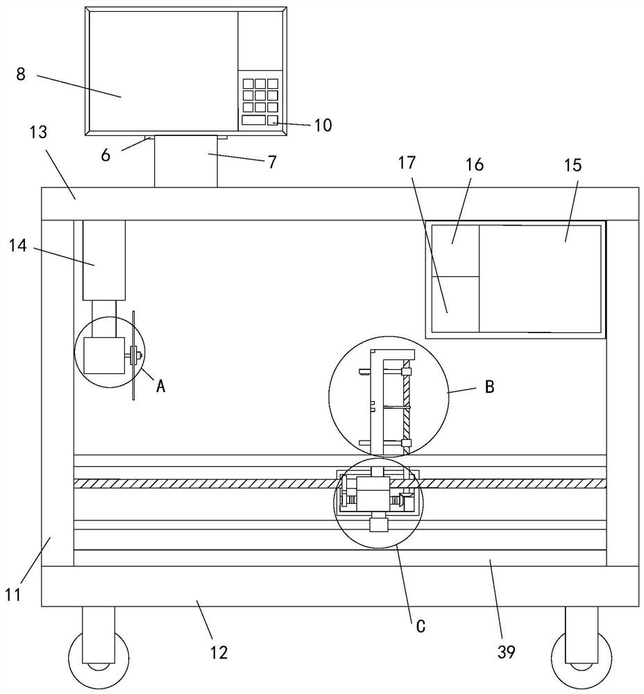
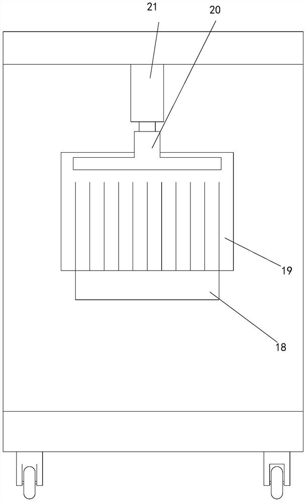
[0039] see Figure 1-7 , a profile sawing device for architectural decoration, comprising a base plate 12, the top left and right sides of the base plate 12 are provided with vertical plates 11, the vertical plate 11 on the left side is provided with a material inlet 18, and each vertical plate 11 The top is connected with a top plate 13, the top of the top plate 13 is provided with a support 7, and the top of the support 7 is provided with a swivel 6, the top of the swivel 6 is provided with a control panel 8, the control panel 8 is provided with an input device 10, the top of the top plate 13 The left side of the bottom end is provided with a telescopic rod one 14, and the bottom end of the telescopic rod one 14 is provided with a motor 27, and the output end of the motor 27 is provided with a saw blade 25, and the left end and the right end of the saw blade 25 are all provided with splint two 24, located at The right end of the clamping plate 2 26 of the right end is provid...


PUM


Abstract

The invention relates to the technical field of building decoration, in particular to a sectional material sawing device for building decoration and a using method thereof. The sectional material sawing device comprises a bottom plate, wherein vertical plates are arranged on the left side and the right side of the top end of the bottom plate correspondingly, a feeding port is formed in the vertical plate located on the left side, a control panel is arranged at the top end of a rotating ring, an input device is arranged on the control panel, a first telescopic rod is arranged on the left side of the bottom end of a top plate, a motor is arranged at the bottom end of the first telescopic rod, a saw blade is arranged at the output end of the motor, a main machine is arranged on the right side of the bottom end of the top plate, a material pushing controller module and a saw cutting controller module are arranged in the main machine, the vertical plates are connected with each other through a bearing plate, a lead screw and a sliding rail, a sliding groove is vertically formed in the top end of the bearing plate in a penetrating mode, a clamping assembly is slidably connected into the sliding groove, and a movement assembly is arranged on the circumferential outer wall of the lead screw in a sleeving mode. Therefore, the sawing position of a sectional material is accurately positioned, the sawing accuracy and continuity of the sectional material are guaranteed, chippings are isolated, intelligent measurement is adopted, and the error rate is reduced.

Description

technical field [0001] The invention relates to the technical field of architectural decoration, in particular to a profile sawing device for architectural decoration and a use method thereof. Background technique [0002] As we all know, architectural decoration is the abbreviation of architectural decoration and decoration engineering. Architectural decoration is to protect the main structure of the building, improve the physical performance of the building, use functions and beautify the building. Various processing processes in space, architectural decoration is an indispensable part of people's life. In the decoration process, some metal profiles are needed as bones, and the bones need to be sawed during use. [0003] The prior patent technology CN209681309U discloses a cutting device for processing aluminum profiles, including a moving work plate, a sliding base, a fixture moving assembly, a moving turntable, a rotating slot, and a saw blade, which can connect clampin...

Claims


Application Information

Patent Timeline
Patent Type & Authority Applications(China)
IPC IPC(8): B23D45/00B23D47/04B23D47/12
CPCB23D45/00B23D47/04B23D47/042B23D47/12
Inventor 向艳清
Owner 向艳清
Learn More