a cable cutter

A cable cutter, one-handed technology, applied to cable cutters. It can solve the labor-intensive and time-consuming problems of manual cutting, and achieve the effects of easy and fast installation, large transmission speed ratio and high output speed.

Active Publication Date: 2022-05-31
浙江坚拓工具制造有限公司
View PDF0 Cites 2 Cited by
  • Summary
  • Abstract
  • Description
  • Claims
  • Application Information

AI Technical Summary

Problems solved by technology

[0002] Many existing cables are manually cut, because the cable has a certain toughness, manual cutting is laborious and time-consuming

Method used


Image

  • a cable cutter
  • a cable cutter
  • a cable cutter

Examples


Embodiment Construction

[0031] The following are specific embodiments of the present invention and the accompanying drawings to further describe the technical solutions of the present invention, but the present invention is not limited to these embodiments.

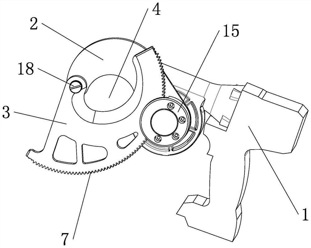
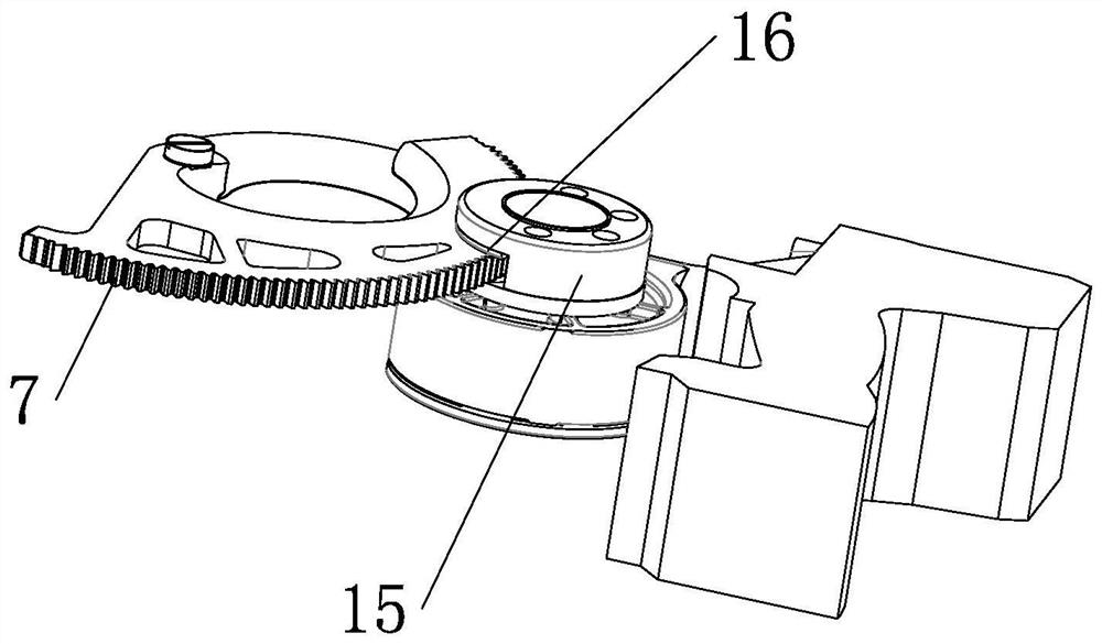
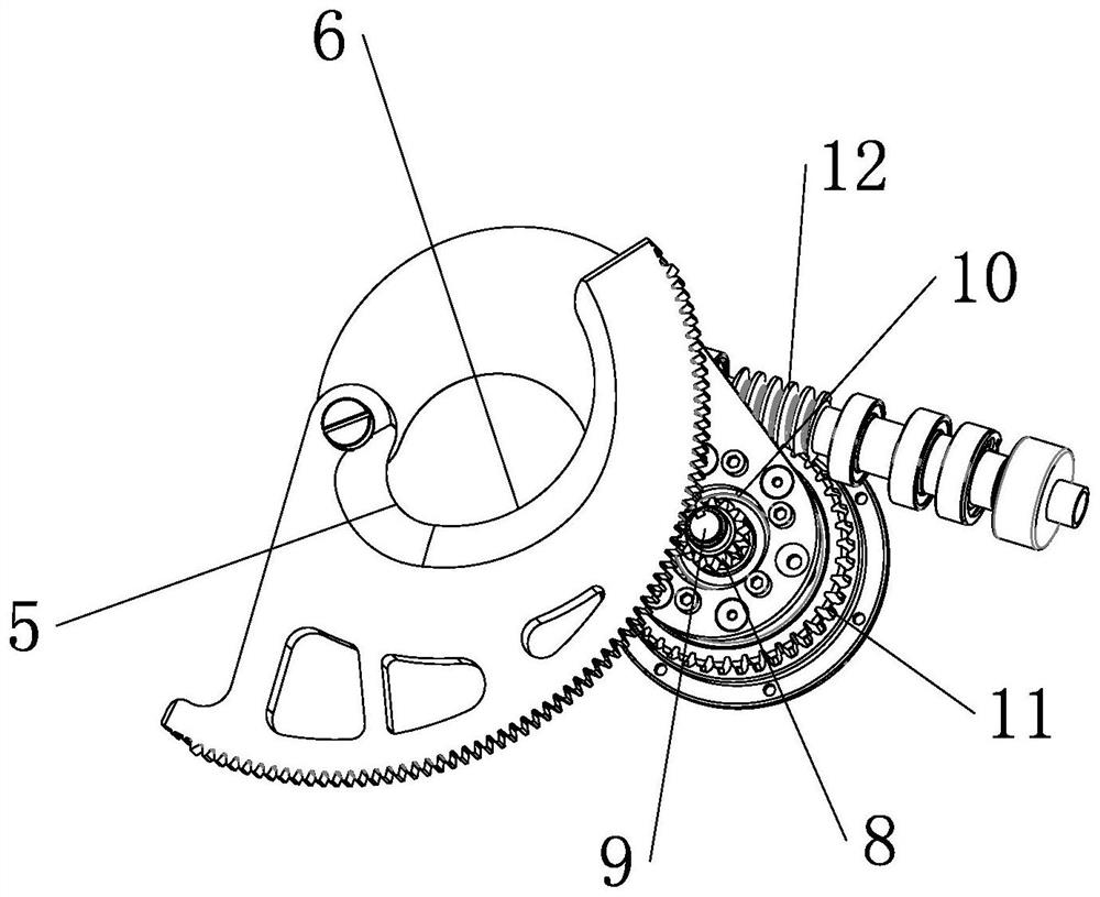
[0032] like Figure 1 to Figure 8 As shown, a cable cutter provided by the present invention includes a handle base 1 and two blades arranged on the handle base 1, the two blades are arc-shaped, the two blades are in contact with each other, and the two blades are divided into a fixed blade 2 and a movable blade Blade 3, one end of the two blades is hinged to each other, the other end of the fixed blade 2 is abutted on the handle base 1, and the fixed blade 2 is fixed on the handle base 1 by fasteners such as bolts, and the other end of the movable blade 3 is freely movable, The width of the movable blade 3 becomes gradually smaller as it extends from its hinged end to the movable end. One end of the fixed blade 2 is the fixed end fixedly connec...


PUM


Abstract

The invention provides a cable cutter, which belongs to the technical field of mechanical shearing. It solves the problems of time-consuming and labor-intensive manual cutting of existing cables. The invention includes a handle base and two blades, the two blades are divided into a fixed blade and a movable blade, the fixed blade is fixed on the handle base, the rotation of the movable blade can increase or decrease the cutting area, the movable blade is provided with external teeth, and the handle base There is a gear and a driving mechanism on it, and the gear and the driving mechanism are connected by a worm gear. The worm gear is set on the handle seat and is concentric with the gear. Press seats against each other. The invention has the advantages of electric drive, labor-saving cutting, smooth cutting, convenient assembly and disassembly, and adjustable gear clearance.

Description

technical field [0001] The invention belongs to the technical field of mechanical shearing, and in particular relates to a cable shear. Background technique [0002] Many existing cables are cut manually. Due to the toughness of the cables, manual cutting is laborious and time-consuming. SUMMARY OF THE INVENTION [0003] The purpose of the present invention is to provide an electric cutter with electric drive, labor saving, smooth cutting, convenient disassembly and assembly, and adjustable gear gap in view of the above-mentioned defects in the existing manual cable cutting. [0004] The object of the present invention can be realized through the following technical solutions: [0005] A cable shear, comprising a handle seat and two blades arranged on the handle seat, the two blades are hinged to each other and the two blades are enclosed to form a shearing area, the two blades are divided into a fixed blade and a movable blade, and the fixed blade is fixed on the handle ...

Claims


Application Information

Patent Timeline
Patent Type & Authority Patents(China)
IPC IPC(8): B23D29/00B21F11/00
CPCB23D29/002B21F11/00Y02W30/82
Inventor 王震
Owner 浙江坚拓工具制造有限公司
Why Eureka
Try Eureka